
Dual René Schmitz Late MS-20 Filter
Introduction
I've always been a big fan of René Schmitz's work. I've been using his VCO3 for years, love his treatment of JH's transistor 2040 clone filter, and, of course, I am a heavy user of his "Late MS-20 Filter" design.
As time has progressed, my use of the Late MS-20 filter design has leaned heavily into utilizing it as a sort of wave shaper/overtone generator as much as a filter.
If this filter is placed in the high pass mode with resonance cranked up to self oscillation, one can feed it a square wave and adjust the cutoff frequency to produce wonderful tones that are both above and below the fundamental sawtooth signal. This results in timbres ranging from almost organ-like to very raw, aggressive sounds. The trick is to allow the filter to track the VCO with no additional modulation.
I've never posted a sample demonstrating this effect, and it is a sample I do need to generate and post. Notwithstanding that, most samples of my modular incorporate this module in one way or another. I have added a sample "Delia" that I generated a few years back with the Klee sequencer that uses the effect extensively.
At any rate, at this writing (Late May, 2010) I would have to say if I were to create this module again, I probably would forgo the improvised "BP" mode. I rarely use that mode, though it is nice to flip the mode switch from LP to BP to HP "on-the-fly" sometimes to radically change the timbre of a voice the filter is processing.
Another thing, I believe, since I wrote this page originally years ago is that I mistakenly believed the HP filter to be a 12 dB filter just as the LP filter is. In truth, I believe now the HP mode is really a 6 dB filter, made more agressive by the recognizable "cruelty" of the unique resonant effect this type of filter produces. In any event, I love this module and would never think of having a modular system without it. -Scott Stites, May 2010
The Dual René Schmitz Late MS-20 filter consists of two separate identical voltage controlled 12 dB Sallen-Key filters interconnected in such a way that the two filters can be operated in tandem as one filter or as two separate filters. The interconnection, which takes advantage of switching jacks, allows three distinct operating modes to be accomplished through 'patch programability'. These three modes are Cascade, Parallel, and Independent.
 |
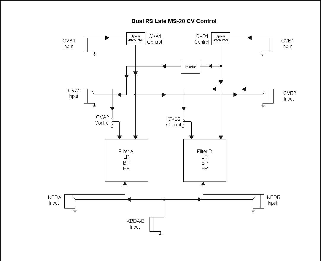
As with the normalled audio configuration, the control configuration is also set up in order to facilitate efficient independent, cascade and parallel mode functionality as well.
Below is a link to the block diagram of the voltage control scheme.
 |
The Filter Blocks
Each Filter block is an individual Late MS-20 filter, as designed by René Schmitz. The schematic for the filter can be found here:
The two filters are designated as Filter A and Filter B. Each filter has variable resonance, one signal input, three control voltage inputs, and one signal output.
Each filter has three different modes of operation: Low Pass, High Pass and Band Pass. These modes are independently switchable for each filter by means of a three position toggle switch for each filter.
Internal Mixer
The module also contains an internal mixer with a single output. The inputs of the mixer are the outputs of each filter.
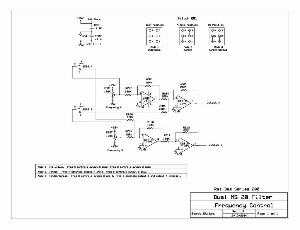
Individual/Tandem/Tandem Spread Switch
The Tandem Switch is a three position toggle switch that selects how the Freq A and Freq B controls work. It utilizes a special kind of DPDT switch - the CK 7211 (a 'normal' DPDT switch will not work here).
When the Tandem Switch is in the bottom 'Independent' (Ind) position, then the Freq A and Freq B controls will operate indepenently of one another. Freq A will control the cutoff frequency of Filter A and Freq B will control the cutoff frequency of Filter B. The Freq A control will have no effect on the cutoff frequency of Filter B and vice-versa. Moving a Freq control CCW will lower the cutoff frequency, and moving a Freq control CW will raise the cutoff frequency of the respective filter.
When set to the middle 'Tandem' (Tan) position, this allows the Freq A control to also control the cutoff frequency of Filter B in conjunction with the Freq B control. In other words, the Freq A control will act as a master frequency control for both filters. The Freq B control can then be used to set an offset between the two filter cutoff frequencies, and the Freq A control will move the two cutoff frequencies higher or lower in tandem.
When set to the 'Tandem/Spread' (Tan/S) position, this allows the Freq B control to also control the cutoff frequency of Filter A - but in an inverse manner. For example, turning the Freq B control CW will increase Filter B's cutoff frequency and, at the same time, lower Filter A's cutoff frequency. Turning the Freq B control CCW will lower Filter B's cutoff frequency and raise Filter A's cutoff frequency. This has the effect of widening (or narrowing, depending on the cutoff frequencies' original value) the distance of one filter's cutoff frequency from the other. The Freq A control will still adjust the cutoff frequency of Filter A and B in tandem, so once a spread is set with the Freq B control, the Freq A control can move the two center frequencies together.
 |
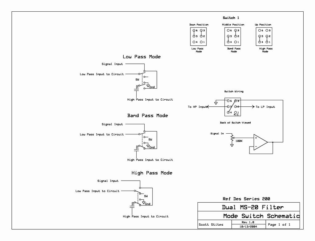
Filter Response Switches
Each of the LP/BP/HP switches use a CK 7211 On-On-On DPDT switch.
The switches are configured so that, when in the down position, the audio signal is applied to the 'normal' low pass input. The high pass input is achieved by ungrounding the grounded end of the second 1 nF capacitor and applying the signal to the ungrounded leg. In this case, we want low pass, so the switch grounds that leg of the cap (the cap shown in the diagram is part of the circuit board itself).
When a switch is placed in the center position, the audio signal is applied to both the low pass input and the high pass input. When in the up position, the signal is applied to the high pass input.
 |
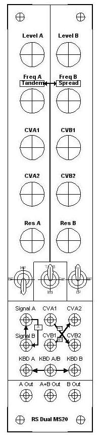
Filter A
The level of the signal input to Filter A is controlled by the Level A control. Full CCW will attenuate the signal completely and Full CW will apply no attenuation to the input signal. The direct input for filter A is the Signal A input jack. If a plug is inserted into the Signal A input jack, the signal on that plug will be processed by Filter A. If no plug is inserted into the Signal A input jack, then any input signal applied to the Filter B Signal Input Jack will be routed to the input of Filter A to facilitate 'parallel' operation. The Level A control will control the level of this signal as well.
The output of Filter A is routed to three destinations: The A Out output jack, the normalled input of Filter B, and the output mixer. Because the signal is routed to the normalled input of Filter B, applying a signal only to the Signal A input jack facilitates Cascade Mode operation. In this mode, the signal is processed by Filter A, then is passed to Filter B for processing, with the cascade output present at the B Out connector.
See the Individual/Tandem/Tandem Spread Switch section above for an explanation of the Freq A control.
There are three control voltage inputs to Filter A - CVA1, CVA2 and KBDA. KBDA is an unattenuated V/Oct input with no associated control. If a control voltage is applied to either the KBDA or KBDA/B input, Filter A's frequency response will track that control voltage.
Any signal applied to the CVA1 input will be processed by the CVA1 control. The CVA1 control is a bipolar attenuating control. At center position, the CVA1 control will attenuate fully any signal applied to the CVA1 input jack. As the control is rotated CCW, the signal level will increase and will be inverted from the original polarity of the input signal. As the control is rotated CW, the signal level will increase, with the original polarity intact.
Any signal applied to the CVA1 input is also sent, after processing by the bipolar attenuation function of the CVA1 control, to the normalled input of CVB2.
Any signal applied to the CVA2 input will be processed by the CVA2 control. This control is a noninverting attenuator. If the control is full CCW, the signal will be attenuated fully, and if the control is full CW, the signal will be unattenuated. If no plug is inserted into the CVA2 input, then the signal applied to the CVB1 will be applied to the CVA2 input, after it has been processed by the CV1B bipolar attenuation function and then through an additional inversion stage. The CVA2 input level control will control the level of this signal before it is applied to Filter A.
The resonance control will apply minimum resonance in the CCW position, and maximum resonance in the CW position.
The three position Mode toggle switch of Filter A allows it to operate in Low Pass, Band Pass or High Pass modes.
Filter B
The level of the signal input to Filter B is controlled by the Level B control. Full CCW will attenuate the signal completely and Full CW will apply no attenuation to the input signal. The direct input for filter B is the Signal B input jack. If a plug is inserted into the Signal B input jack, the signal on that plug will be processed by Filter B. If no plug is inserted into the Signal B input jack, then any input signal processed by Filter A will be applied to the input of filter B. Therefore, with a signal only applied to the input of Filter A, this facilitates Cascade Mode operation. The Level B control will control the level of the processed Filter A signal applied to its input in this mode.
Any signal applied to the input of Filter B is normalled to the input of Filter A before being processed by the Level B control to facilitate cascade operation.
The output of Filter B is routed to two destinations: The B Out output jack and the output mixer. With a signal applied to only the Signal B input jack, the signal is processed by both Filter A and Filter B in parallel. The outputs of both of these filters are mixed by the output mixer and the Parallel Mode output is present at the output of the mixer, A+B out.
See the Individual/Tandem/Tandem Spread Switch section above for an explanation of the Freq B control.
There are three control voltage inputs to Filter B - CVB1, CVB2 and KBDB. KBDB is an unattenuated V/Oct input with no associated control. If a control voltage is applied to either the KBDB or KBDA/B input, Filter B's frequency response will track that control voltage.
Any signal applied to the CVB1 input will be processed by the CVB1 control. The CVB1 control is an attenuating/inverting/noninverting control. At center position, the CVB1 control will attenuate fully any signal applied to the CVB1 input jack. As the control is rotated CCW, the signal level will increase and will be inverted from the original polarity of the input signal. As the control is rotated CW, the signal level will increase, with the original polarity intact.
Any signal applied to the CVB1 input is also sent, after processing, by the bipolar attenuation function of the CVA1 control, through an additional inversion stage to the normalled input of CVB2.
Any signal applied to the CVB2 input will be processed by the CVB2 control. This control is a noninverting attenuator. If the control is full CCW, the signal will be attenuated fully, and if the control is full CW, the signal will be unattenuated. If no plug is inserted into the CVB2 input, then the signal applied to the CVA1 will be applied to the CVB2 input, after being processed by the CVA1 bipolar attenuation function. The CVB2 input level control will control the level of this signal before it is applied to Filter B.
The resonance control will apply minimum resonance in the CCW position, and maximum resonance in the CW position.
The three position Mode toggle switch of Filter B allows it to operate in Low Pass, Band Pass or High Pass modes.
The KBD inputs
The KBD 1V/Octave inputs consist of KBDA, KBDA/B and KBDB. The KBDA and KBDB inputs are normalled to the KBDA/B input. If a plug is inserted into the KBDA/B input, the signal present on that plug will control both Filter A and Filter B in tandem. If a plug is inserted into the KBDA input, then Filter A will track only that signal. If a plug is inserted into the KBDB input, then Filter B will track only that signal.
Independent Mode Operation
The module can operate as two independent filters in one module. Any signal applied to Signal A is processed by Filter A, and the output of Filter A is present at the A Out jack.
Any signal applied to Signal B is processed by Filter B, and the output of Filter B is present at the B Out jack.
The Independent mode can also be used to mix two separate processed signals together - the output of both filters are internally mixed and present at the A+B Out jack.
The control voltage normalling scheme is designed so that any interaction between control voltages between the two filters in this mode can be easily defeated. This is the reason CVA2 and CVB2 or not "inverting attenuator" controls. Signals are normalled to them, and one may not wish to have those signals affect the filters when these inputs are not being used. It is much easier to fully attenuate the normalled signal by turning the control full CCW rather than find the spot in the middle that is 0 attenuation on an "inverting attenuator". CVA1 and CVB1 have no signals normalled to them, so their position is a non-issue when no signal is applied to the them.
Moreover, the V/Oct KBD inputs can be fully independent by simply using the KBDA input and/or KBDB input instead of the KBDA/B input.
Cascade Mode Operation
The module can be easily configured to Cascade Mode by applying a signal to the Signal A jack and tapping the output at the B Out jack. To accomplish this mode, no plug should be inserted into the Signal B jack. The signal applied to the Signal A jack is first processed by Filter A, then by Filter B. Be sure to adjust the input level of Filter B to allow the signal from Filter A to pass through it.
This mode can be used to facilitate a variable width band pass filter by setting Filter A's mode to HP and Filter B's mode to LP. The signal then passes through Filter A, cutting all of the frequencies below the cutoff, then it passes through Filter B, cutting all frequencies above the cutoff. The width of the band pass can be adjusted initially by adjusting the Freq controls of Filter A and Filter B. Filter A's cutoff must be lower than Filter B's cutoff in order to achieve this response.
Placing the Tandem switch in the 'Tandem' position allows filter cutoff frequencies to be adjusted with one master control. When in the 'Tandem' mode, the Freq A control will also control the cutoff frequency of Filter B. The Freq B control can then be used to tune the initial spacing between the filter cutoffs. For example, if one wanted the cutoff frequency Filter B to be 100 Hz above Filter A, one would adjust the the Freq B control so that the response of Filter B was 100 Hz above the response of Filter A. Then, adjusting the Freq A control would move both filters' cutoff frequency in tandem, keeping the 100 Hz offset intact. This is a convenient feature for using the filter in the Cascade and Parallel modes, because once the offset is set, one control can be used to quickly adjust both filters at the same time, in the same proportion and in the same direction.
Placing the Tandem switch in the 'Tandem/Spread' (Tan/S) position allows filter cutoff frequencies to be adjusted with another master control, the Freq B control, but this control moves the center frequency of each filter in opposite directions.
Moving the Freq B control CCW will raise Filter A's cutoff frequency and lower Filter B's cutoff frequency. Moving the control CW will lower Filter A's cutoff frequency and raise Filter B's cutoff frequency. The Freq A control will still adjust the cutoff frequency of both Filters A and B in tandem.
Any of these modes, Independent, Tandem, and Tandem/Spread, can be used to set the cutoff frequency relationship between the two filters A and B.
The control voltage input scheme is optimized, through the normalled inputs of CVA2 and CVB2 for controlling the center frequency and bandwidth (the difference in cutoff frequencies of both Filter A and Filter B).
A control voltage present at the CVA1 connector, with no plug in the CVB2 connector, will modulate both filters' cutoff frequency in the same direction. The setting of the CVA1 control will set the intensity and direction of the control voltage's effect. The setting of the CVB2 control will determine how much effect the setting of the CVA1 control will have on Filter B's cutoff frequency. As an example, when configured for a series band pass response, this setup will control the center frequency of the composite filter.
A control voltage present at the CVB1 connector, with no plug in the CVA2 connector, will modulate both filters' cutoff frequency in opposite directions. The setting of the CVB1 control will set the intensity and direction of the control voltage's effect. The setting of the CVA2 control will determine how much effect the setting of the CVB1 control will have on the Filter A's cutoff frequency. In the composite series bandpass filter example, this control voltage application will modulate the bandwidth of the filter. A positive voltage, with the CVB1 control set in the non-inverting range of control, will widen the bandpass response by lowering the frequency of Filter A (set in the high pass mode) and raising the frequency of Filter B (set in the low pass mode).
Connecting a CV to KBDA/B will allow the response of both filters to follow a single V/Oct control voltage. Applying a CV to KBDA will release Filter A from the KBDA/B voltage and allow it to follow this control voltage. The same principle applies to Filter B for any CV applied to the KBDB input.
Besides deriving a band pass response through Cascade Mode operation, it is also possible to achieve a filter with a higher order of cutoff. Each filter section has a 12 dB response. Cascading the filters while each is in the same mode will increase this to a 24 dB response. Non-linear filter functions can be realized by offsetting the initial freqencies and resonances of each filter. Different combinations of filter modes are possible with this mode as well for unusual filter responses.
Parallel Mode Operation
The module can be easily configured to Parallel Mode by applying a signal to the Signal B jack and tapping the output at the A+B Out jack. To accomplish this mode, no plug should be inserted into the Signal A jack. The signal applied to the Signal B jack is internally sent to the Signal A and processed by Filter A. The signal is also processed by Filter B, and the outputs of both filters are combined in the internal mixer. The individual outputs are also available on the A Out and B Out connectors for further processing or stereo connections.
This mode can be used to realize a variable width band reject filter, or 'notch filter'. To implement this, one filter can be sent to LP and the other to HP. The low pass cutoff must be set lower than the high pass cutoff. The frequencies between the two cutoffs are then not allowed to pass, creating a notch in the response. The closer the cutoff of both filters are to each other, the narrower the notch.
Another use for Parallel Mode Operation is to use the same filter mode for each filter, or two different modes for each filter, and have them move in opposite directions. When the two filter responses meet in the frequency domain, the timbre can be quite interesting.
The controls and combinations of controls discussed in the Independent Mode and Cascade Mode descriptions apply to this mode of operation as well.
Sound Samples
In the introduction to this page, I mentioned using the dual MS-20 as a sort of waveshaper/octave generator when it is in the HP mode with high resonance. The following sample (entititled Delia) uses such a patch. The metallic "springy" sounds are the result of passing a sawtooth through a section fo the dual late MS-20 filter module and cotnrolling the cutoff through that section's KBD filter with the same signal that controls the pitch of the oscillator, making certain that no other modulation is applied to the filter. With this patch, one can slowly rotate the filter section's cutoff control and listen as certain intervals "lock in" to the waveform. Once a desirable interval is heard, one then need only control the filter as described.
Here's a sample using the MS-20 filter in the dual filter bandpass mode. Filter A is in high pass mode and Filter B is in low pass mode.
I recorded a sync track on the D8 and used Ray Wilson's Signal to Gate Circuit to extract gates from that signal. With that signal, I trigger an 8 step sequencer and an AD envelope generator to control the filter and the VCA. Each voice on the sample is a single sawtooth VCO going through both filters in cascade mode, through a VCA, through some reverb from the Sidekick amp straight into the D8. When I recorded the sample, I wasn't intending on demonstrating the filter, I was more intent on experimenting with the technique of sequencing using a recorded signal as the gate source, but then I realized I haven't posted any samples of this filter yet, so....here it is =0).
In other words, this is really only a glimpse into the sonic capabilites of this filter.....
This next sample uses the Signal to Gate circuit again, but with a bit of a twist - I modulated a VCO which was triggering the Buchla SOU 266 Stored Random circuit with an output of the stored random circuit - this created a stuttering series of pulses. In fact, the sample opens up with the actual sync track that I used - it sounds a bit like (I assume) nosensical Morse Code. I added some of the high triangle sequence from the above sample to it as well.
The following is a composition using the same technique as the previous samples. A sequence of 8 notes was programmed on the sequencer and synced using the same method. The same pattern is overlaid on five tracks, only each track varies in time signature, voice and octave. As in the first sample, I recorded at a fast sequence of pulses and used a CD4013 flip flop to divide the recovered pulses by two and four.
I again used the MS-20 filter, but also used the CGS wave multiplier on the 'bass' of the sequence and on the high jangly notes of the sequence. Most of it is the modular, but I added some background pads using the Korg DW6000 through my Korg PS3XXX Resonator circuit, which was modulated by an LFO.
The lead lines were mainly just triangle, pulse and sawtooth through the MS-20 Filter.