
Looney Mod For Ray Wilson's Wacky Sound Generator (WSG)
Foreword
In late 2005, as is my custom, I brought up the Music From Outer Space website just to check out what Ray Wilson was up to (he's always up to something, you can guarantee that). What did my wandering eye alight upon but a brand new entry - the Wacky Sound Generator circuit.
If you've been in this electronic geek game any time at all, you already understand there is no shortage of noise boxes. But the WSG is special; whereas some noise boxes are marketed as a "synthesizer", the WSG actually comes closer to that defintion than the vast majority of those boxes out there.
Why is that? Well, the thing that bugs me most about the standard "noise box" is the sheer unrelenting raw sound of the pulse wave(s) it generally produces. Sure, some waves modulate others, but they are still the same, ultimately tiring waveforms. To me, a synthesizer is an instrument that can produce a wide range of sound, not just endlessly crushing noise and glitch. In other words, would it kill someone to put a filter in a circuit like that?
Well, it certainly didn't kill Ray, because he created something worthy of being built and played with and sampled for ring tones and loved and cuddled. The WSG. It has a cool filter and plenty of cool guts to keep one occupied and un-bored for....well, forever.
At the time I saw this, Ray hadn't come up with a PCB yet. It was more feasible at the time to apply these modifications. On perfboard or protoboard, it would be easier to build one section as a WSG, and leave the other section open to take advantage of the thereby unused sections. That's what originally got me going on the Looney mod, and I had a blast doing it.
Even though one does not care to use these mods to modify a WSG, a lot of the practices on this page may hold you in good stead with your own sound circuit experiments. Optocouplers are insanely easy to apply to just about anything. They're the synth world's version of duct tape. Once you have a standard circuit that you use to suck the current out of or blow the current into the LED, you can tack the optocoupler anywhere within a circuit you want to work your sleazy magic. This page exposes some very simple methods for doing just that.
Editor's Note
The following mods use devices referred to as 'Vactrols'. 'Vactrol' is the trademarked name of an optoisolator, also referred to as optocouplers, formerly manufactured by Vactec, now manufactured by Perkin-Elmer. An optoisolator is a single, light-proof package containing an LED and one or more Light Dependent Resistors (LDR). An LDR, or photocell, has a resistance that varies with the amount of light striking its surface. In the case of the optoisolator the amount of current passing through an LED determines how brightly the internal LED shines, which affects the resistance of the LDR built into the same case. Note that these devices are not the same type of device that contains an LED and a light sensitive transistor or diode, it must be an LDR.
Different optoisolators have different characteristics - the value of 'on' resistance, the value of 'off resistance', and, just as important, the amount of time it takes for the LDR to reach its 'on resistance' from a state of 'off resistance', and the amount of time it takes the LDR to reach its 'off resistance' from its 'on resistance'.
Some LDR's take longer to reach these two states than others. Some manufacturers make LDR's that are very, very fast. Others are very, very slow. All LDR's will normally take less time to go from light (on) resistance than time it takes to go to dark (off) resistance. These time factors can be thought of as the 'attack' and 'decay' of the optoisolator.
For these mods, particular attention should be placed on the maximum dark resistance - these LDR's will go in parallel with 1M pots, so ideally the off resistance should be quite a bit greater than that, yet have a fairly low on resistance.
A great source of information on these devices is Perkin Elmer itself:
Perkin Elmer are not the only manufacturers of such devices. It may pay to visit Silonex and study their optoisolators - there may be faster devices or just plain different curves to their devices that may be fun to try:
A good source of the optoisolators discussed on this page is Allied Electronics:
And let us not forget Small Bear Electronics, the flagship of DIY. Steve Daniels can hook you up with Vactrols, and about a zillion other hard-to-find items at a good price.
It is also possible to 'roll your own' optoisolator by combining an LDR of your selection along with an LED into some sort of light resistant package. Some have used heat shrink tubing, others have resorted to other methods.
Motohiko Takeda demonstrates his method, plus some fascinating info here:
Here's an article I wrote on how to experiment with 'rolling your own':
And, finally, here's Grant Richter's writing on a particular application:
DisclaimerThe Colorado Institute of Wackology or its Kansas Extension, The Lunar Goofological Research Association, cannot be held liable for any psychological disturbance thought to be inflicted by the WSG device, either upon its builder or its builder's family or neighbors. Proceed at your own risk.
December 28, 2005: The Dawn of Looney
Today I decided to have some fun and try out Ray Wilson's Wacky Sound Generator. I'm glad I did, it's a lot of fun. Here's the link to Ray's design:
I was pleased with how much mileage Ray got from a simple Hex Schmitt Trigger and a 741 op amp - and that, Ray is only utilizing half the CD40106 for one section of the WSG!
I was also surprised with how good the simple filter Ray had devised for the generator sounded. The thought crossed my mind that it would be cool to control the cutoff dynamically as well. Controlling the cutoff was the easy part (ye olde Vactrol crutche), but what to control it with? Ah, how about the Zany frequency generator?
So, I grabbed the first Vactrol I could find - a VTL5C2, of which I have several, a 2N3904 transistor, a 56K resistor, a 2K resistor, and a 50K....dang, can't find one, OK, a 100K pot. I applied the control circuit, a bit of knowledge I gleaned from Grant Richter's Wogglebug3 schematic, and put the LDR leads across the 1M Oddness Cutoff Frequency control.
I then connected the control end of this new 'filter intensity' pot to pin 6 of the CD40106, and voila - I got a nice pulsing filter sound with the Zany frequency. I then put a jumper between pin 6 of the CD40106 to pin 13, thus inverting the Zany signal and tried that - a real nice variation on the sound! Now, what to call it? The Loony control? And, a Loony switch - a three position SPDT, center off. Up would be noninverted Loony and the down position would be inverted Loony (Sane?).
The VTL5C2 may not be the best choice, but then again, it works OK. It's a sloooowwww Vactrol, so it tends to smooth out the sharp transients of the Zany signal and make them more 'wah-like'. Because of the slew of the VTL5C2, the intensity of the effect dies away at higher frequencies. Other contenders will be neat to try - the venerable and much loved VTL5C3, for example.
Another take would be to create a copy of the Zany frequency section on an unused portion of the VTL5C3, thus having independent Lunacy. Still yet, another use for the last unused gate would be to put a momentary one-shot on it, and kick the filter in the butt with a press of the button (a way to fire 'notes' as it were).
Here are a couple of 'on-the-fly' samples of the Loony control:
In Lunacy 1, I vary the intensity of the Zany's effect on the filter. It starts off in the 'inverted Loony' mode. At around 00:54 I start to change it to noninverted Loony - I had to move an alligator clip, and it took me a while (it's a cramped l'il breadboard). Once the change is made, you can hear the difference.
In Lunacy 2, I start out with Noninverted Looney. At around 1:15 I switch to inverted Looney. Now pay particular attention to this transition - I accidentally brush against the input of the pot with the alligator clip, giving it a 'one shot' - notice how this accidental pulse forms a note (right after that, I successfully latch onto the wire and the inverted looney takes over). That's what gave me the idea of the one-shot kick in the butt. Again, throughout this sample, I vary the intensity of Zany's effect on the filter.
December 29, 2005: Enter the Twang
Today I added a 'Twang Switch' and an associated "Twang Intensity Control". Nothing fancy - just a normally open momentary switch that feeds +V into the Vactrol control circuit through a pot configured as a voltage divider. No need to worry about debouncing - the Vactrol (at least the VTL5C2 I'm currently using, and most likely any other Vactrol) is slow enough that any type of switch bounce wouldn't even begin to register.
As mentioned above, I'm still using the VTL5C2 - I just haven't dug out a VTL5C3 yet. As it stands, the VTL5C2 puts a nice little envelope on any press of the twang switch. In fact, whatever Vactrol is put there will determine the nature of the twang switch - the response curve of the Vactrol will directly translate to the filter envelope. With the VTL5C2, one can quickly punch the switch without giving the Vactrol a chance to rise to its full on resistance. Holding the switch down does. In this manner, the control can be rather expressive. It's a lot easier to manipulate than the cutoff pot, but with certain settings, it can sound like you're twisting the pot rather than punching a switch.
The 'Twang Intensity Control' is quite useful, it allows one more precise control. Generally, this control can be set to the maximum cutoff frequency desired, and from there the switch does the rest.
Below are some samples of the twang switch in action, with various Wacky settings, Loony settings, and Twang Intensity settings. The samples demonstrate the slow 'on time' and the much slower 'off time' of the VTL5C2.
December 30, 2005: Rise of the VTL5C3
Today I fished a VTL5C3 from my stores and plugged it into the circuit. The change is actually quite dramatic. The envelope of the VTL5C3 has a much shorter attack and decay than the VTL5C2. The VTL5C3 is the 'golden Vactrol' that figures so prominently in the Buchla circuits - the 292 Low Pass Gate and the 291 Band Pass Filter. The response curve of the VTL5C3 closely emulates naturally occuring percussive envelopes.
In this application, the VTL5C3 delivers sharper attacks and decays, though still slewed. The slew rate is low enough that low audio modulation of the filter cutoff is possible, allowing a new range of timbres to emanate from Ray's brainchild. The VTL5C3 is very good at manipulating the lower notes to give them more 'thump' and less 'click'.
Installing the VTL5C3 required that I re-examine the resistor at the emitter of Q1L - with the VTL5C2, 1.33K worked very well. This, however, did not allow enough current through to force the VTL5C3 to low enough resistance. I decreased the resistor to 1K, then to 680 Ohms. This nudged the VTL5C3 more into the sweet spot.
The '5C3 turns the Loony mod into a different thing. I really like it, but then again, there are aspects of the VTL5C2's response that I like as well. Being a cake-and-eat-it-too kinda guy, I figured out a solution that would allow one to have both in one WSG if one wanted it. I'll put it on schematic later, but the idea is this: run the LED of a 5C3 in series with the LED of a 5C2, then connect one lead of both LDR's to one point on the cutoff pot. The other two leads could go to a switch that would select which Vactrol was placed in parallel with the pot. This would allow one to have a Thumpy and Mushy switch =-D.
The decreased emitter resistor value would push the VTL5C2 to be a bit more sensitive in adjustment, but it wouldn't be all that bad. It's certainly an option for those of you out there that are like me - you like a lot of switches and knobs and, morever, you actually *use* them.
While on the subject of knobs and switches, I thought I'd also mention I like jacks, lots of jacks. One obvious jack for this critter would be a CV input. It would be very, very simple to normalize a CV input to the Twang control. Then people lucky enough to have Sound Lab's (or other synths) could patch an LFO into this thing and control the cutoff with that.
Another jack would be one to apply a footswitch to the cutoff frequency - a momentary footswitch to be exact. This would allow one to tweak knobs with both hands and 'twang' with the foot.
And, back to switches, a nice little addition would be a switch to put the +V on the Twang Intensity control constantly. This way, when Twang wasn't being used, the intensity control could set the center point of the Zany signal which is modulating the cutoff. Better yet, if one wanted, an offset pot could be added instead of the switch. It would be set up as a voltage divider between +9V and ground, with the wiper connected to the base of Q1L through a 56K resistor. This would allow one to set the point 'twang' started from, the center point of the modulation AND allow any external bipolar CV to be offset by this control and scaled by the Twang Intensity control. Sound Lab mates with WSG perfectly......
One final thing. This easy method of putting stuff under voltage control could be applied just as easily to other controls in the WSG........
So, after all this blather, here are some samples of the Loony mod using the VTL5C3 instead of the VTL5C2 - if you compare them to the previous samples, it'll be obvious how different the filter cutoff manipulation really is between the two devices.
Jan 02, 2006: Project Daffy
Is it 2006 already? Dang, better add a another Synth Diary. If it contains as much text as Diary '05, well, that won't take much =-D.
Back to the Wacky project. Code Name Daffy applies another crude Vactrolism to the WSG. This mod attacks the Weird Frequency control in the same manner Loony went after the Oddness Cut Off Frequency control. In other words, the LDR of a VTL5C3 is placed in parallel with the Weird Frequency pot and the LED is driven again with the Zany Frequency control.
In this app, nothing slower than a VTL5C3 works very well, so the VTL5C2 is out on this one. Also, the sensitivity of the control should be kept a little lower, as smaller deviations of Weird seem more effective than larger deviations. So, the emitter resistor of Daffy is set at around 2K or so. This is, of course, open for experimentation, so you might want to tell Igor to go rob a few different values out of your resistor graveyard before you hoist your WSG up to the lightning rod.
The other control again determines whether Daffy is controlled by Zany or inverted Zany. This creates variation because it allows one to set whether Zany is rising while the filter is falling or falling while the filter is rising, or combinations thereof. An optional Zany twang could be installed so that the press of a button would cause zany to rise and be held each time the zany twang was pressed.
Tech Speak:
Daffy tends to elicit some nice 'formant' type tones when used in conjunction with Loony. If Wackiness is shut off, one can get some nice bubbly sounds if Loony is twanged during longer periods of Zany.
Below are some samples of Project Daffy in action. This is without a Daffy Twang switch - no room at the Breadboard Inn.
Operation Kooky
The implementation of Code Name Kooky is as kooky as its name. Kooky consists of a crude optically implemented Zany Controlled Attenuator, or ZCA for short. It's as simple as they come and performs its task without changing the core of the WSG. 'High Tech' would not be a term that comes to mind when studying Kooky (as if Loony and Daffy fall into that category). In order to work its evil, Kooky worms its way onto the output of the circuit. I don't think Kooky alters the output impedance of the circuit too drastically, and it provides a spiffy new function - it uses Zany to form individual 'notes' with either a twangy or klunky sounding envelope, depending on the other WSG settings. The Kooky Intensity control controls how much Zany knocks Kooky around, and the Initial Kooky level control allows one to dial in how much signal is allowed to pass through initially. This is accomplished by using the LDR and a 10K resistor as a voltage divider. As the current through the LED increases, the voltage at the junction between the LDR and 10K resistor increases and vice versa. Being a simple voltage divider, the voltage will never fall completely to 0, as with a 'normal' VCA, but it drops far enough in level as to be inaudible, especially with all of the constant WSG happenings going on in the meantime. Again, a VTL5C3 or faster (IE, not a VTL5C2) works best in this app.
So, say you dial up the Initial Kooky level to max, the operation is pretty much as the 'normal' WSG (with Loony and Daffy optionally in place). Did I just say normal? Huh. Anyway, dial up the Kooky intensity and dial *down* Initial Kooky, and only the pulsing Zany level allows the signal to pass through Kooky. Of course there's a range of in-between, depending on the relative settings of the two controls. It works like any standard 'real' synth VCA, with Initial Kooky being the offset control, and Kooky Intensity being an input attenuator to the CV input of the VCA, which is actually the Zany signal. Cranking Kooky Initial up and down during operation of the WSG (which should only be done with protective gear) allows part of the signal to fade in and out, sometimes allow the WSG to 'accompany itself' with the other half of the Zany pulse, and at other times just forming discrete notes. Well, you have to play with it (or try to interpret the following samples).
Kooky is also greatly enhanced by either being controlled with Zany or Inverted Zany, especially when mixing and matching with Inverted and Non-Inverted Controlled Loony and Daffy. This is where experimentation with the finished product (preferably by robotic arm in a reinforced enclosed container) will be a lotta fun.
A Kooky Twang switch could be added so that the amplitude could be gated on and off manually. This could be optionally tied to the Loony twang so that the filter and amplitude follow each other, though I would not hardwire it this way - I'd make it switchable. So, what is that now, anyway? 150 controls? Well, not that many, but its obvious one could create a lot of little tweakables on these additions.
So, here are some samples of Kooky in action. In each sample, I adjust the initial Kooky up and down so one can hear the difference between fully on WSG and gated WSG for comparison. You many notice that the envelope has alternately a 'woody' and 'twangy' character. This is the response of the VTL5C3 peeking through. The fourth sample, particularly, takes on an almost banjo-like character. All of these samples were made with Loony and Daffy already in place. Only the Loony filter twang switch was used (I don't have a Daffy or Kooky twang switch wired up). As with all the samples on this page, no effects were used.
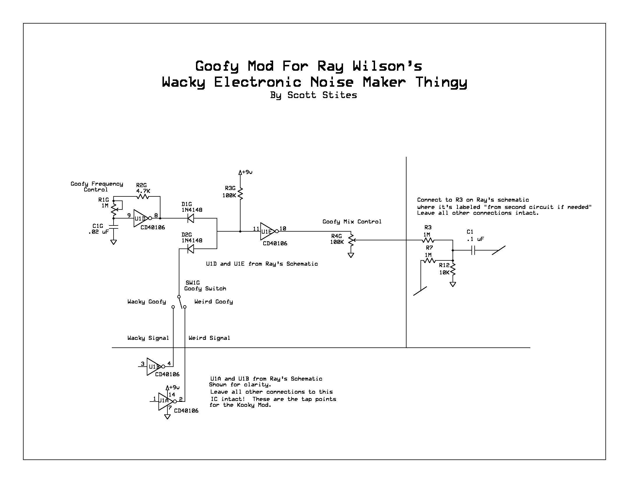
Frankenloon Meets Count Wackula: Codename Goofy
I just couldn't resist messing around with the circuit even more, and came up with some more Wackiness extensions.
The first extension involved using up the remaining two sections of the CD40106. One section is used to create another oscillator, copied directly from Ray's Wacky oscillator. This generator I've named Goofy. The last available section of the CD40106 is converted into a Mickey Mouse NAND gate using the MML logic that Ray has written up on his page here:
This NAND gate is used to combine either the Wacky oscillator or the Weird oscillator (selectable by a switch) with the Goofy oscillator to form the composite Goofy voice in two flavors. One input of the MML NAND gate takes either Wacky or Weird, and the other gate takes the Goofy signal. Combining the signals with a NAND gate renders a sound reminscent of a ring modulator (though true digital ring modulators utilize an EXOR gate). This Goofy voice is mixed in with the Zany Wacky Weird signal at the input of the filter through a 100K pot. This allows a variable mix of Goofy with the rest of the gang.
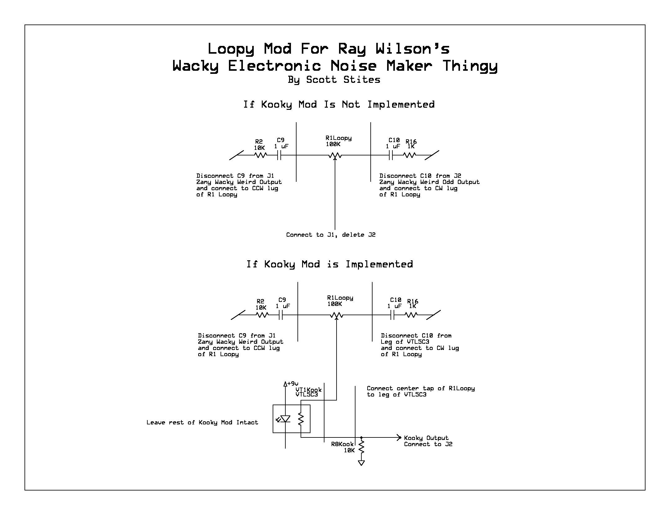
The Loopy Effect
Throughout all of this, one thing has been ignored - the original Zany Wacky Weird output. This is a cool sounding output by itself, and quite different because it is unaltered by the filter. Loopy takes advantage of this and takes it one step further. Loopy is a simple control that cross fades the Zany Wacky Weird Loony Loopy Odd Output (ZWWLLOO, or Zwaloo) output with the Zany Wacky Weird Output (ZWWO or Zwo). The idea to do this actually occured to me for another reason. Look at Zwaloo - its harmonic content is altered by the filter. But, there is one other major distinction - its phase is inverted in relation to Zwo.
Because Zwaloo is low pass filtered and inverted, combining it with Zwo creates a high pass response of sorts when the cross fade is within a certain range - so its higher frequencies fade in first over the top of low passed Zwaloo. All the way CW, you have Zwaloo, all the CCW you have ZWO, and throughout the middle you have a crossfaded, quasi-high passed mixture of Zwaloo and Zwo. Note that Goofy is only included with Zwaloo, so the more Zwo, the less Goofy. Make sense? If it does, you are either in need of some serious help or have earned an honorary degree of Wackology =-D.
Loopy is extremely easy to implement - in fact, if you just implemented that and none of these other mods, it would still give you an increased variety of sound out of your WSG.
To put together your basic loopy control, simply connect ZWO to one side of a 100K pot, Zwaloo to the other side of the pot, and the center tap is the ouput. The output of Loopy is placed right before the Kooky ZCA, so Kooky still controls the amplitude of the composite signal. If you don't have Kooky implemented, then the output of Loopy would go straight out to the outside world.
Obviously schematics are in order. They're on their way......
In the meantime, here are samples of the WSG in action with Goofy and Loopy. These samples concentrate mostly on those functions.
In the first sample, the Loopy control is varied from Zwaloo to just a bit of Zwo (just so one can get used to what it actually sounds like).
The third sample, towards the end, is a good example of some cool sound reinforcement (on the low note) by having Goofy close to or at the same frequency as the....um....others.
The fifth sample is a pretty good example of where one goes with the thing and how twiddling things elicits the different faces of Wacky. There are some good examples of Wacky 'formants' starting around 3:11 or so. Neighbors beware.
DEEP FRIED WACKY: Feel the Crunch
Don't case that thing up yet. I've cranked the beast up to the lightning rod, and this time she took a terrible jolt. When the platform was lowered, I saw movement, and, as the smoke cleared, I spotted another appendage. Wacky had grown a new mod, a mod so hideous, so transmogrifying, so horrifying that.....
Well, yes, anyway. There's a new mod, Codename Crunchy.
It's ridiculously easy, BTW.
Here are some samples, a small taste of the range of new timbres. As with all of the samples on this page, no effects, no multi-tracking used (except for the first which was inadvertently modified by my Dim C/TZF). It's just mainly Wacky blowing chunkage.
The Schematics Trickle In.....
The link below contains the second revision of the schematic for the Loony mod. It's exactly as it on the breadboard right now. It's a very simple (simplistic) mod, but it's quite effective, I believe. There's a small bit of interaction between the Loony Intensity and Twang Intensity controls, but that's what makes these kinds of things fun =0)
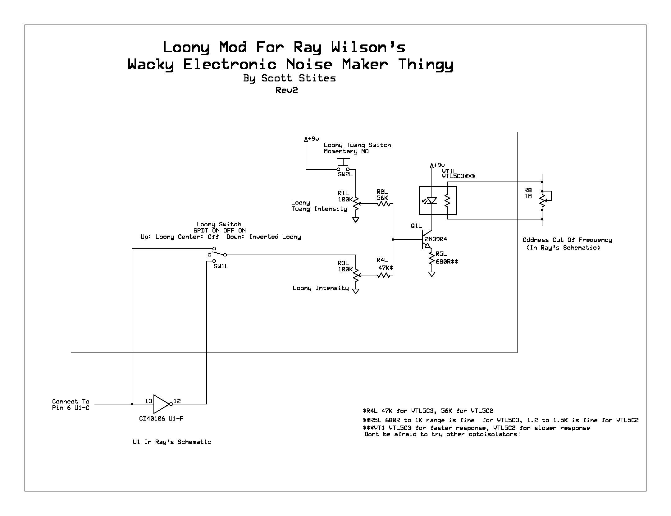 |
Below is the link for the 'Deluxe Loony Mod'. This demonstrates how to make the circuit switchable between a VTL5C2 and VTL5C3 response.
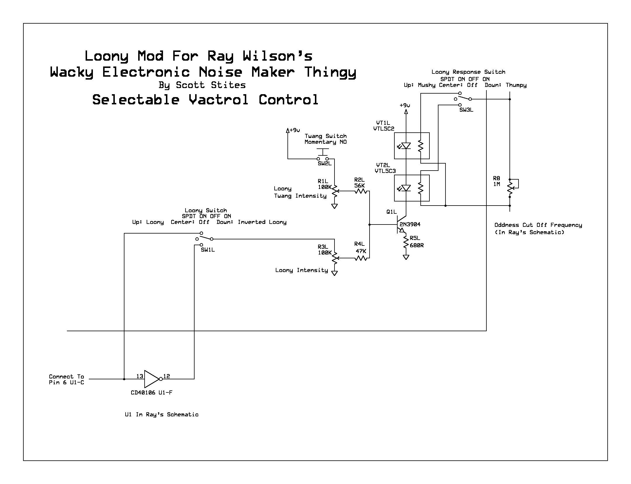 |
Following are the rest of the mods used on this page.
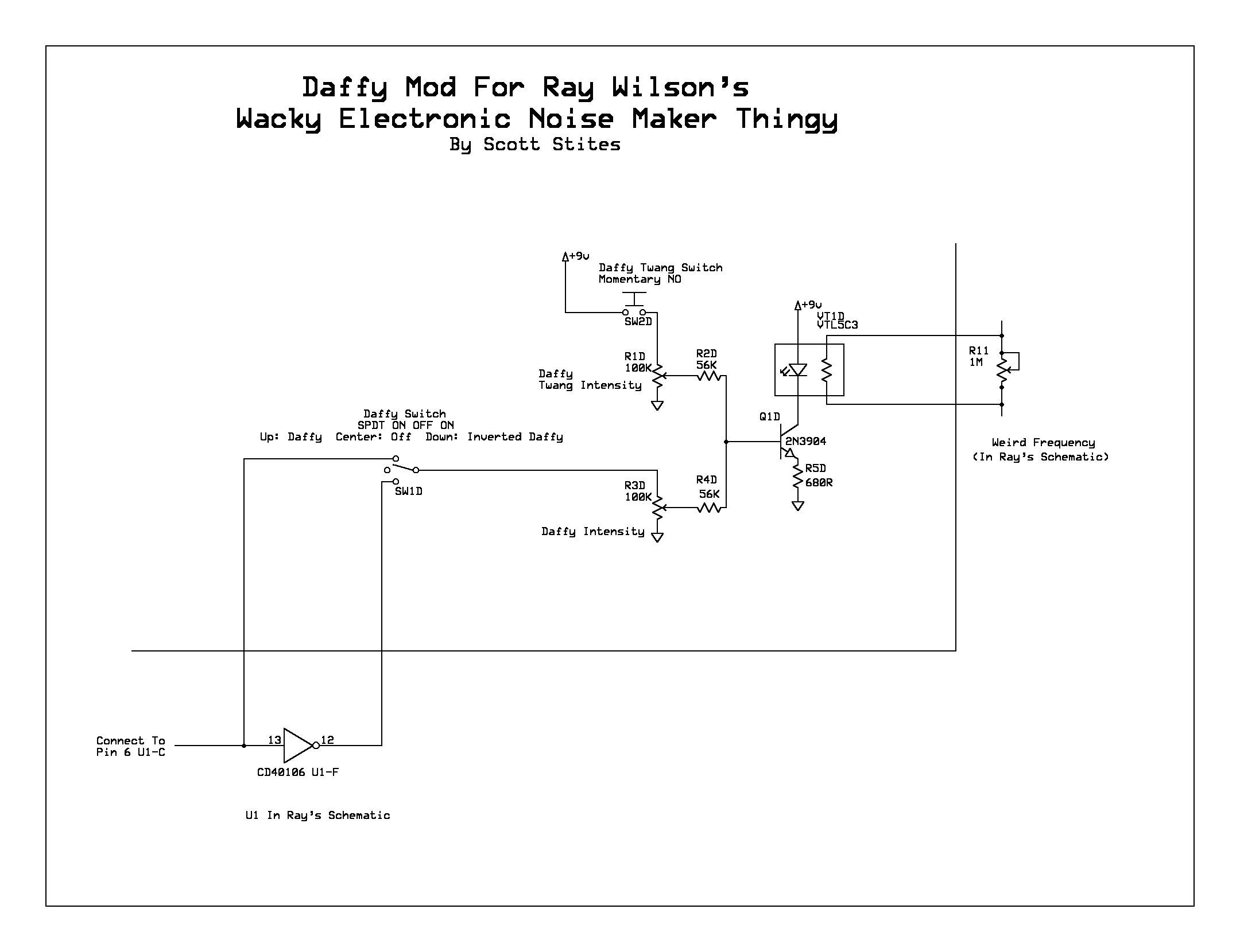 |
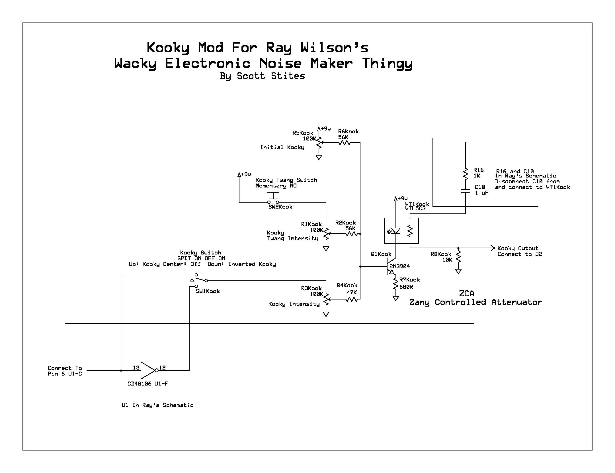 |
 |
 |
 |
You'll notice there are a lot of controls when you add up all of these mods. Not all of them are required, it's more of a 'pick and choose' moment here.
Before I switched over to the VTL5C3 for Loony, I had the VTL5C2 on there for those samples. I think on my final build, I will have the 'both' option.
Controls used to make the samples (besides the original RW controls):
Loony Mod:
Loony Intensity Control, Twang Switch, Twang Switch Intensity, Loony/Inverted Loony Switch
Daffy Mod:
Daffy Intensity, Daffy/Inverted Daffy Switch
Kooky Mod:
Initial Kooky, Kooky Intensity, Kooky/Inverted Kooky Switch
Goofy:
Goofy Level, Wacky Goofy/Weird Goofy Switch
Loopy:
Loopy Control