
The 8038 Audio Generator Project
An Accurate 20 Hz to 20 kHz Linearly Controlled Audio Generator
I can't remember how many times I've heard the ICL8038 described as anything from being merely "OK" to "An overheating waste of sand". This is hardly a surprise - the 8038 has always had backing it a datasheet that puts it in the situation of having to crank out a modest frequency range while providing a certain more-than-warm glow to keep the engineer or technician warm throughout the winter. In other words, the poor thing can't help but start out on the wrong foot when someone refers to the datasheet for guidance on how to use the thing.
So, our 8038 has been consigned many a time to sit out the game on the bench. All it needed was a good coach, someone habitual enough to pluck it off the bench and force it to run wind sprints, stair laps and line drills. And that certain someone was Coach Henry.
As it turns out, what the 8038 needed was a good change of diet. Instead of junking out on positive voltage rails, Thomas fed it a steady diet of good old fashioned negative rail. For +V Thomas gave it a nice vitamin enriched ground potential, and for the pin formerly known as ground, a nice fibery -12V. That alone catapaulted the 8038 from mediocrity to true A Number One function generator-hood.
Thomas then bulked it up with carefully chosen components, and *Voila*, may I introduce you to an audio generator that not only goes from 20 Hz to 20 kHz, but goes from *exactly* 20 Hz to 20 kHz. And, all the while, this little champion maintains its sine, triangle and pulse outputs to a "T".
Parts of the circuit may look familiar to you - Thomas had an earlier version of it posted on Midwest Analog for some time. When Midwest Analog closed down, it was....appropriated....without permission by another entity. For a while, unauthorized PCBs for the earlier version were sold, until Coach Henry spotted the rogue board and put it to an abrupt end. After that, Thomas took that basic circuit and created this much improved and superior design.
So, you may ask, what is this audio generator for? Is it a piece of test equipment or a component for a synthesizer? The answer to that question is "Yes."
On this page you will find complete plans for the function generator - a schematic, a PCB layout, and plans for a nice, spiffy case to put it in. That allows you to put it on your bench top and use it to test your audio circuitry. It has voltage input - it's a linear response, not a V/Oct response, but, with it's Electronotes standard 10V peak to peak output, it can also be used as an audio or modulation source for your modular synthesizer. Though it does use linear control voltage, it's doubtful it would track a linear voltage produced by, say, a keyboard of a Korg MS-20, which produces a linear control voltage, but it would be great for sweeping and modulation effects. On the electronics bench, this input would be great for tests that require a swept oscillator. For example using a scope with XY inputs and sweeping the audio generator with another VCO to check out the response of a filter.
Features
The audio generator operates in the the range of exactly 20 Hz to 20 kHz. It features sine, triangle and square wave outputs. The frequency control set consists of a coarse and fine tune arrangement - the coarse control obviously will move the frequency in greater increments, and the fine control allows one to set the frequency exactly at the desired point.
In addition to the front panel frequency controls, the audio generator also accepts an external control voltage in the range of 0 to +12V. An input attenuator is provided to scale this voltage to the desired range of control.
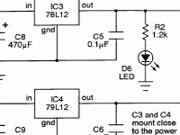
Finally, the schematics include a +/-12V power supply to power the audio generator, so that the audio generator can operate as a completely stand-alone unit.
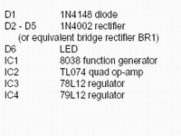
Schematics and Parts List
There are two pages to the schematic - page one features the audio generator circuitry, and page two features the +/-12V supply that can be included with the audio generator.
Each of those schematic pages, plus the parts list can be downloaded below.
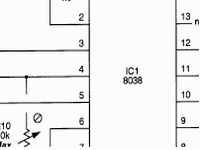 |  |  |
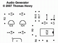
As you peruse the schematic, you'll find the typical elegant economy of of a very effective design that is Thomas' virtual trademark. Note that there are only two integrated circuits used in the audio generator! This is not a difficult project to build.
PCB Files
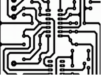
If you'd like to etch a PCB for your audio generator, the PCB layout and parts placement document are available for download below.
 |  |
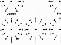
A Housing For Your Project
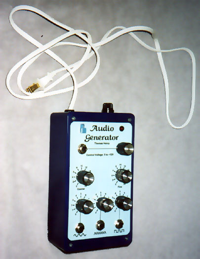 |
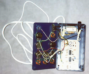
Here's a pic of Thomas' completed project (you can click on the image to enlarge it). This approach turns the audio generator into a handy portable device you can take out to the field (or to a gig!).
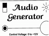
The panel decal can be made from the panel document provided below, and Thomas has also supplied a drilling guide for it, which can also be downloaded.
 |  |
Circuit Description and Calibration
We'll start off with the general topology that Thomas has put into place. Notice the 8038 (IC1) is placed in the negative feedback loop of IC2a, and that the 8038 is being fed ground as it's *positive* supply, with -12V replacing ground on pin 11. As Thomas puts it:
The negative supply voltage trick is done to reference the control input to ground. That is, doing it the data sheet way with a positive supply, means that the CV is awkwardly referenced to V+. Doing it my way references the CV to ground. Much more convenient!
This is the main bulk of the magic Thomas has devised to make the 8038 play super-nice. The rest of IC2 (sections b, c and d) all serve to level shift and place the output levels of the various waveforms at +/-5V, centered about ground.
It should be noted that you will probably want to use a good quality pot for R25, the Coarse control. In fact, if you are going to use a scale for that pot on your panel, this will be essential. Even though the marks on Thomas' panel design are only approximations to help find the ballpark, a better quality coarse pot will put you closer to those marks.
Notice there are a number of trimpots - these are in place to ensure that the specified frequency range is met, while maintaining the correct linear waveforms of the triangle and sine outputs throughout that range.
There are five trim pots. Two trim pots are used to set the maximum and minimum frequency range of the audio generator. R10 sets the maximum frequency and R23 sets the minimum frequency.
Three trimpots are used to calibrate the quality of the waveforms - two set high frequency and low frequency symmetry, while another trims the distortion of the sine wave. R1, Symmetry Trim sets the symmetry of the waveforms above 100 Hz or so. R22 is the Low Frequency Symmetry Trim - it is used to ensure the waveforms hold their symmetry below 100 Hz. Once the symmetry is good across the frequency range of the audio generator, R21 is used to trim the distortion of the sine wave to the lowest possible level.
The calibration is more or less an "around the horn" affair - one has to go back and forth a few times between trimpots before everything is set. An oscilloscope is pretty much required for setting symmetry of the waveforms. Distortion may be set by that most precise piece of equipment you possess (the set of ears you have placed on each side of your head), or an oscilloscope, or a combination of the two. Frequency may be set with a counter, though I personally used an oscilloscope when I had it on the bench (as my counter has been defunct for some time).
1. While monitoring the square wave output on a scope, at around 5 kHz, adjust R1 (Symmetry) to give a 50% duty cycle.2. Drop down to 50 Hz or so and adjust R22 (Low Frequency Symmetry), again for a 50% duty cycle.3. Go back and forth between these two pots until you get good symmetry at the low and high ends.4. Turn R25 (Coarse) and R26 (Fine) to their highest settings. While monitoring the output on a frequency counter, adjust trimmer R10 (Max) to give 20 kHz.5. Turn R25 and R26 to their lowest settings. Adjust R23 (Min) to give 20 Hz.Go back and forth between these to pots to arrive at a solid 20 Hz to 20 KHz range.6. Go back and forth between these to pots to arrive at a solid 20 Hz to 20 KHz range.7. While listening to the sine output and watching it on a scope, adjust R21 (Sine Distortion Trim) for minimal harmonic distortion. This is easy to do with ears alone.8. Repeat the entire sequence a couple times to lock in all trimmers as desired.
Resources
Obviously, there are just not a whole lot of parts in this project, and all are fairly easy to get hold of. The 8038 seems to be the most elusive of the parts, though it's not all *that* elusive.
I'd say your best bet for the 8038 is BGMicro (a very cool little outfit that supplies all kinds of spiffy stuff for this obsession of ours). Other places have it as well, though I was disappointed to recently discover I couldn't get them at Jameco, a place I'd always relied on before for my 8038 procurement. Abra Electronics, Debco, Futurlec, Unicorn - they all have it. Shop around - prices vary widely!

As always, there is the Thomas Henry Designs forum at electro-music.com. I urge you to go there and browse, and even sign up (hey, it's free!). A great group of guys, including TH himself, are known to hang out there.
Magic Smoke is now making available Thomas' new publication "A Synthesizer For the 21st Century". This publication is available for preview and purchase at Lulu.com - inhaling this particular Magic Smoke icon will take you there. What does this have to do with the Thomas Henry 8038 Audio Generator Project? Welllll......if you check out this marvelous publication (which is a complete set of schematics for an entire synthesizer) you will find that at the heart of a very, very cool LFO circuit rests our little buddy, the 8038. You'll see it is fed the proper nutrients as well.