
The Voltage Controlled Quadrature Function Generator Project
A Unique Voltage Controlled Quadrature Function Generator
Through the years, Thomas Henry has designed a lot of synthesizer circuits - you name it, he's designed at least one version of it - VCOs, envelope generators, VCAs, filters, sequencers, flangers, phase shifters, drum voices...pretty much the gamut of things that make our synthesizers tick. All of them have his indelible mark of a carefully considered level of functionality coupled with a high standard for the elegance of the design - in other words, Thomas hates to open cans of beans with dynamite.
All of these circuits are worthy of your synthesizer, so it's hard to find any one or more of those circuits to differentiate by calling it truly "classic" over the others, but if I had to, there are certainly a few that I would choose. One of them would be his Supercontroller circuit; another, in my opinion, would be the relatively new SN-Voice. But, surely included in this group would be his Quadrature Function Generator. What makes it a classic to me is the approach Thomas took, which was, well, ninety degrees out of phase from any other approach to generating quadrature waveforms.
What is A Quadrature Waveform?
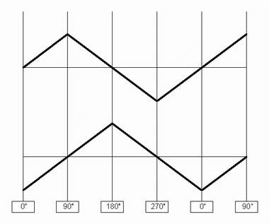
To have a quadrature waveform, you really need at least two waves. The first wave could be said to be at 0 degrees, and the second wave could be said to be in quadrature with that wave - in other words, the quadrature waveform is 90 degrees out of phase to the zero degree waveform. The frequency of both waves is the same - it's the offset in phase between the two waves that defines the function.
Figure 1 illustrates this offset - notice how the lower triangle waveform crosses the center line 90 degrees "behind" the upper triangle wave.
It's easy enough to get two waves at the same frequency and one hundred eighty degrees out of phase - that only requires simple inversion - the 180 degree waveform is merely the exact opposite of the 0 degree waveform. But, to get an offset of 90 degrees, well, that takes some doing.
In order to obtain a 90 degree offset from one wave to the next, one method would be to provide some way of shifting the phase of the signal in some manner. An all pass filter, used in the phase shifters we're all so familiar with, can shift a signal ninety degrees. But, that 90 degree phase shift would only occur at a particular frequency for a given set of component values. If one took that route, one would be reduced to either settling for having a fixed frequency or one would have to devise some method of controlling the phase in concert with the frequency. Or, one could use several all pass stages and build a complex "dome filter", which certainly would be just as much overkill as trying to make a phase shifter track the frequency of an oscillator.
A more standard method is to create an oscillator that generates the two signals in quadrature. Most synthesizers already have such an oscillator - a resonating four pole filter is capable of producing a quadrature sine wave at the second pole of the filter in relation to the sinewave produced at the fourth pole of the filter. However, this signal is rarely made available through the front panel. As an aside, Thomas's design, the TH-201 Mankato Filter marketed by Magic Smoke Electronics provides such quadrature outputs.
The problem with quadrature oscillators is frequency and amplitude stability often can fall short of expectation. What was needed was a more stable *function generator* capable of generating quadrature waveforms.
It was this problem that Thomas was addressing when he formulated his approach. Never having seen an earlier design that used his method, I asked him where he'd come up with the idea, and this is was his reply:
I derived the results mathematically back in 1981 while at the U of Iowa, using the notion of composition of functions, and then implemented those electronically. Electronotes #122 gives the complete analysis, and it's quite interesting and accessible.
Of course, the sign changer FET trick had been used before for creating ramps from triangles (by Bernie* and others), but again, I believe I was the first and perhaps the only one to create a triangle from a triangle.
*The Bernie mentioned, of course, would be the incomparable Bernie Hutchins of "Electronotes" fame.
I've seen the mathematical work Thomas went through to prove the design, and, it's not only beyond the scope of this web page, it's quite frankly beyond the scope of my brain. For those interested in the details, Electronotes EN122 is still available. The design (minus most of the mathematical analysis) was also published as an article in the February 1984 issue of "Polyphony" magazine, and later in Thomas' book "Build a Better Music Synthesizer" (1987, Tab Books, Inc.).
The best way I have of describing Thomas' approach is that he designed a function generator that produced a triangle wave, then he took that triangle wave, and sliced it, inverted it at exactly the right time, and diced that. Then he put the pieces of sliced/diced triangle back together again to form - another triangle wave. Another triangle wave that was exactly ninety degrees out of phase from the original triangle wave, that is. Thus, he had the stability of a function generator, and he had the quadrature output.
Of course, any new approach inevitably presents a new set of problems to deal with. For Thomas to pull this off, the lines of the pieces of triangle would have to line up perfectly when the new triangle was formed. In a perfect world, that wouldn't be a problem - but this is not a perfect world. All electronic parts have a finite amount of nonlinearity in them, and these nonlinearities tend to move things around - a rising slope may not be as perfectly pitched as a descending slope, for example. Without adequate measure taken to compensate, these nonlinearities can put 'pips' in the lines where they are joined together again.
In Thomas' original design, he exploited the fact that the 741 op amp is a real dog when it comes to slew rates. The 741 just couldn't flip around as fast as these pips occurred, so the pips were minmized to the point of negligibility. In this newer design, Thomas minimizes them with a filter circuit instead - now, the design is no longer dependent upon a certain op amp's slew rate.
And, of course, this newer design has changed quite a bit to accomodate the one thing that would really put it over the top for a synthesizer application - he put the frequency of the function generator under voltage control, with an exponential volts per octave response. And, unlike the "Polyphony"/"Build a Better Music Synthesizer" version, in which Thomas mentions that a couple of inverters could be added to derive the 180 degree and 270 degree outputs, this one has those outputs included. Finally, this version has indicator LEDs for each output - and quadrature signals make a very cool LED display.
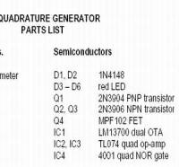
Schematics, Parts, PCB
When you examine the schematic, you'll probably think "What, that's it? That's all it takes?". This my common reaction to any of Thomas' designs. With his designs you can rest assured that (A) It will contain exactly what it needs to operate correctly and (B) It will work. That's why beta-testing for Thomas is such a breeze, really - experience taught me long ago he never sends anything that's "just an idea" or a "I wonder if this would work" thing. It first must work for him exactly as he expects, or I never see the design. The beta testing is just to confirm that no reliance on any part which would affect the consistency of operation has been overlooked.
Clicking on the little pictures below will allow you to view or download PDF files of both pages of the schematic as well as a parts list.
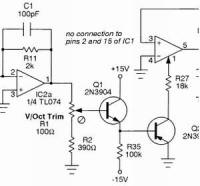 | 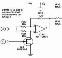 |  |
IC1 provides the voltage controlled triangle core oscillator of this circuit. IC1a, Q1 and Q2 form the expo frequency control circuit of the oscillator. IC2b processes the triangle to provide the 0 degree output, IC2c inverts this signal to form the 180 degree output signal. IC2d is configured as a comparator, used to drive the samurai-chop-the-triangle-up-and-toss-it-in-the-air logic, which is orchestrated by IC4, leading us to the "big note" of this construction:
Be careful to note the power connections to IC4: notice it is powered from ground and the negative rail of the circuit!
Q4 and IC3a form the all important sign changer required to manipulate the original triangle to the right phase at the right time for chopping. IC3b is used in the function that connects the two disparate triangle sections together. C4 and C3 around IC3d form the smoothing filter that serves to eliminate the connection 'pips' on the derived triangle. IC3c inverts the derived 90 degree waveform to form the 270 degree waveform.
Construction Notes and Calibration
To calibrate the volts per octave response, replace the 0.47 uF timing cap (C12) with a smaller value (like 0.001 uF) and tune it by ear while adjusting R1. The calibration for this is as with any VCO circuit - you adjust R1 so that you get a transition of one octave per every volt applied to the V/Oct control input.
That leaves the Offset and Connect trims (for those of you familiar with the previous QFG design, you'll notice the "Skew" trim has been eliminated by this design).
If ever a calibration could be considered fun, this would be it. The offset calibration is self-explanatory - you adjust R39 to center your 90 degree derived waveform around 0V (ground).
The Connect trim (R40) is the fun part. Look at Figure 3 and Figure 4. These scope shots illustrate the 90 degree derived output before calibration and after calibration. Figures 3 and 4 can be examined more closely by clicking on them to enlarge the pictures.
Be sure to set the frequency to a high enough frequency so that it can be observed on your oscilloscope. Before calibration, when you connect the 90 degree derived waveform to your oscillscope, you'll see something like that depicted in Figure 3 - it may look more or less different, depending on the intial settings of R39 and R40.
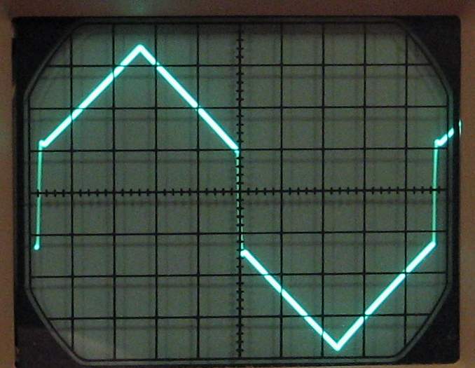 | 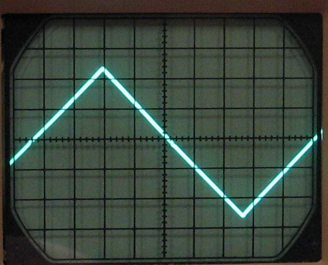 |
Figure 3: The 90 Degree Output Before Calibration | Figure 4: The 90 Degree Output After Calibration |
As you adjust R40, the two halves of the chopped up triangle wave will join or "connect" together to form the derived 90 degree waveform, as can be seen in Figure 4. You may have to adjust the offset trim (R39) as you complete this process.
A Few Final Circuit Notes From Thomas Henry
Thomas mentioned the following to me:
"...with regard to the timing cap, the value shown of 0.47 gives a top rate of 150Hz. This is perhaps more than needed for control purposes, so a person could replace it with a 1uF non-polarized to get 66Hz max, or even 2.2uF to get 30Hz. By choosing the lowest useable oscillation rate, of course, one gets a better symmetry at the low end. For my system I'm going to go with a 2.2, for I just can't imagine wanting more than 30Hz for control. In any event, the oscillator covers some ten octaves easily."
I would certainly agree. I found that for really low frequencies (0.1 Hz and below) having a larger value for the timing cap certainly worked much better, especially for the symmetry of the waveforms. I would say between 2 and 3 uF is plenty. I personally used some Mylar caps for this (I have a nice supply of 1 uF Mylar caps that I got cheap from Electronic Goldmine a few years back, I just tried them in parallel for the higher values).
For the intended application of the VCQFG, a lower frequency range does make sense. As Thomas puts it:
"....the 1V/octave business is great for sequencer/rhythmic things; just think in terms of period now instead of frequency. For example, if 1V equals a period of 6 seconds then 2V will be a period of 3 seconds. If a person has a two bank (parallel) sequencer (like my old SuperSeque), this means that the A row can control the pitch of each note, while the B row controls the duration (quarter note, eighth note, etc.). Since we're talking time now and not frequency, a simple expo is good enough, and there's no need for the thermistor. (Ears are sensitive to frequency but not period)."
Applications for the VCQFG
Thomas' mention of the use of the VCQFG with his SuperSeque design above is just one of a plethora of applications. Consider that, with this module, you have access to four triangle waveforms that are at the same frequency, but have rise and fall segments offset symetrically over time.
Figure 5 illustrates the four outputs of the VCQFG. Notice how at any given time, you will have some waveforms rising, while some are falling, and all are constantly at some different point in their cycles. This can be used to great effect for some wonderful stereo or quadraphonic effects.
In fact, in his original articles, Thomas discusses using the QFG for "Location Modulation". The idea is that you can send a common signal to four different VCAs, and have each phase of the QFG control each of these VCAs. The effect, when using each VCA as a separate channel, is of the signal moving around you in space.
Even stereo effects using 90 degree quadrature can be stunning. Quadrature modulation can be used to create stereo effects devices, for example. Driving two phase shifters, flangers, or chorus devices in quadrature creates a unique and compelling stereo effect. And try driving two filters in quadrature! Even driving two devices in quadrature can create unique mono effects.
And, how about using the QFG to create control signals? Imagine the four outputs driving four comparators to create four gate signals symetrically spaced over time? How about two, three or four S&H circuits sampling each output from a common clock signal? As with many analog synthesizer modules, the imagination is often the only limitation to its application.
Sound Samples
I have yet to generate any new samples with the VCQFG. In the meantime, here are a couple of samples from my "MultiPhase Journal" page. I used a sine shaper to distort the quadrature outputs to a hypertriangular shape (in fact, the same circuit used in Thomas' VCO-1 design, miscalibrated for a wide bottom and narrow top). Here is the description of the two samples:
Each of the following samples consists of three sections:
1. Phase Bank B modulated by a hypertriangular wave with no phase offset to Phase Bank A.2. Phase Bank B modulated by a hypertriangular wave with a 90 degree offset in relation to the hypertriangular wave modulating Phase Bank A.3. Phase Bank B modulated by a hypertriangular wave with a 180 degree offset in relation to the hypertriangular wave modulating Phase Bank A.
The source of the sound is a plain-Jane, unmodulated voice from the DW6000, which is going into the MultiPhase circuit mono and each bank is connected straight to the recorder (no FX used).
0, 90, and 180 Degree Modulation, Slow Sweep, High Res
0, 90 and 180 Degree Modulation, Fast Sweep, Low Regeneration
Finding Parts and Other Resources
There are no hard-to-find parts in the Voltage Controlled Quadrature Function Generator. In fact, all of the ICs could be found at Debco Electronics in a one-stop visit.

The original Quadrature Function Generator article is available as EN-122, which can be obtained through the legendary Electronotes series. Visit the link below to get more detail and to order your set of Electronotes.
Magic Smoke Electronics makes available the fabulous TH-201 Mankato filter which, besides being an "instant classic" of a filter, also provides sine outputs in quadrature. Click or inhale the Magic Smoke logo to be there or be square.

The Electro-Music Thomas Henry Designs Forum is an invaluable resource for obtaining information, assistance, and sharing your experiences and music created with Thomas' designs. Please don't hesistate to join in and get involved! With a single click on the Electro-Music logo below, you shall be transported there.
![]()