
SN-Voice Construction and Calibration
Construction Notes
Important Note: The SN-Voice uses +/-15V and +5V supplies. To avoid damage to the SN76477, pay special attention to the power connections when building the SN-Voice.
The SN-Voice contains a number of front panel connectors and controls. This means that a large part of the build process will involve deciding what panel arrangement you choose to use and, of course, actually wiring up these panel components. The circuit itself is relatively simple, particularly if you have purchased an SN-Voice PCB. Once you have the PCB or circuit board assembled and wired up to your SN-Voice Panel, a final calibration will be required to properly deliver you to SN-Voice Land.
Panel Pot and Switch Wiring
In order for all of the pots to operate as described in the Operations section of this page, the pots must be wired as illustrated in the document below. Left click the thumbnail to display, right click to download.
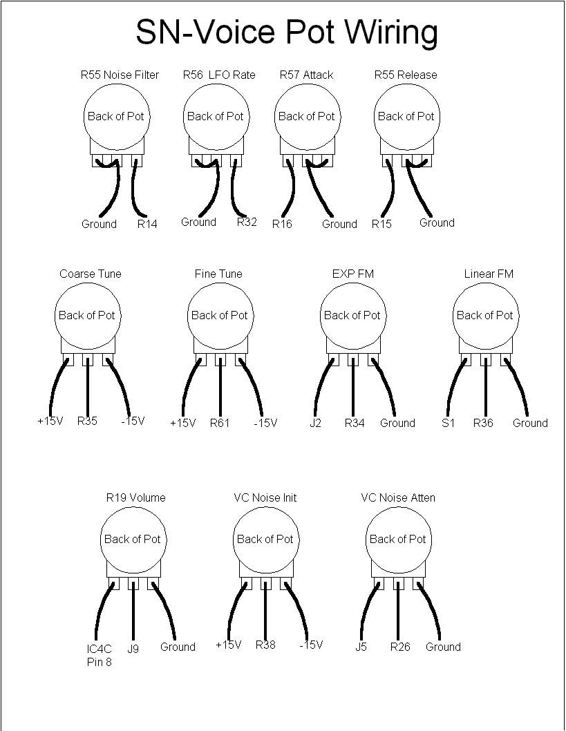 |
If panel space is a concern, or if you just prefer toggle switches to rotary switches, below I've posted a link to an illustration that demonstrates how one can use the C&K 7211 On-On-On switch as a three selector switch - it can be used for S5 (PWM) and S4 (LFO Range).
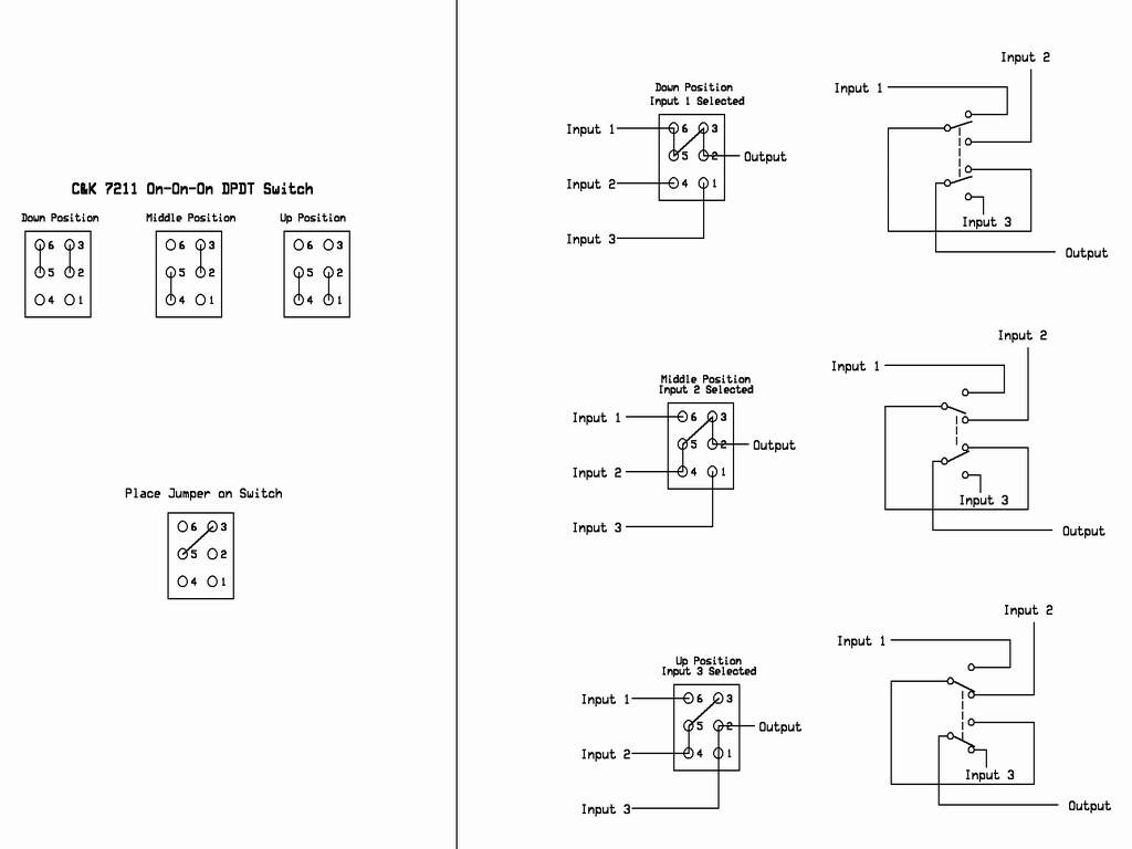 |
Calibration
There are three parameters of operation that will need to be calibrated once your SN-Voice is assembled:
- Modulation Center Trim
- Triangle Wave Offset
- V/Oct Response of the VCO
Modulation Center Trim
The Modulation Center trimpot (R18) is set as follows: While listening to the pulse output and letting the LFO modulate the PWM, adjust trimmer for smoothest variation. Near the center of rotation, the transition is linear. Move away from the sweet spot and the modulation is lopsided or nonlinear.
Alternatively, one can watch the triangle wave on a scope and adjust this trimmer to give a +/-5V amplitude. This should correspond to the smoothest modulation, too.
Thomas and I have found that the voltage at pin 16 of the SN76477 will be between 0.5V and 0.44V.
Triangle Wave Offset
Observe the triangle wave output on an oscilloscope and adjust the Offset trimpot (R29) so that the triangle is 10V peak to peak and centered at 0V.
V/Oct Trim
The SN76477 was never designed for a V/Oct response, so don't be surprised if you have to put a little extra work into it as compared to other VCO's. Thomas and I don't expect a whole lot of chip to chip variation - I tried a 'wide body' model and a 'narrow body' body SN76477, and Thomas tuned up a wide body SN76477 with a diferent date code than mine with similar results.
You may find that tuning by ear will render the best results.
First of all, the V/Oct trim should not be attempted until the Modulation Center Trim adjustment has been performed. Begin by setting the the HF trimpot (R58) for maximum resistance (1MOhm).
Tune the V/Oct trimpot (R2) as one normally adjusts a VCO. First tune the V/Oct trim between 60 and 120 Hz until as close an octave as possible is rendered with a 1V signal (IE, with the VCO at 60 Hz, increase the control voltage by exactly 1 volt and ensure the VCO is at 120 Hz). Next, tune for an interval between 60 Hz and 240 Hz, and so forth.
Get the best tuning you can up to 2 kHz - you'll most likely have to go around the horn several times to coax the best response out of the SN76477. Resist tweaking the high frequency compensation until you've gotten the best response up to 2 kHz.
Thomas wrote this to me:
I found in this VCO that the HF trim could be used to help straighten out the response somewhat lower than usual. My suggestion is to say: Ignore HF completely until you've done the best you can do. Then tune to 2KHz, augment with the HF trim and start dropping octave by octave and see what impact that had. Then start upping octave by octave into the 4KHz range and split the difference (things are probably going sharp by this point and need to be reduced.)Of course, this may all change somewhat if we end up working from a PCB version. I noticed that the control current input wire on the breadboard was extremely sensistive to stray capacitance. I think a PCB is going to make this a lot more fun to tune.