
SN-Voice Schematics and Documentation
Introduction
The SN-Voice schematics presented on this page are the final version Thomas and I worked out. Thomas did most of the work. My contribution amounted to a couple of "can we try this" ideas. If I worked out any circuitry for what it was I wanted to try, and it worked for me, I'd send it to Thomas. If it flew, Thomas would incorporate the idea, but in a much more elegant way than I could ever come up with - he invariably would take my idea and get it working with around a third of the parts I'd slopped in.
This version of the SN-Voice is designed to be as stable and predictable as possible. There were certain things that had to be 'traded off' in order to maintain the expo tuning and frequency stability. For example, one trade-off had to do with being able to vary the pulse width, yet maintain the top end of the frequency range, without causing undue shifting in frequency when PWM was applied. Without the PW stuff, the top end of this thing would go up in excess of 15 kHz, according to my frequency counter. With the added pulse width stuff, we became limited to around 7.5 kHz, which is plenty for this application anyway.
The Schematics
Important Note: The SN-Voice uses +/-15V and +5V supplies. To avoid damage to the SN76477, pay special attention to the power connections when building the SN-Voice.
Click the picture below to download a zip file containing the schematics, parts list and a panel design by Thomas.
 |
The VCO Exponential Converter
The exponential circuit is very similar to the one Thomas devised for the XR-VCO - it utilizes an NPN transistor pair (LM394) and a 2K 3500 PPM tempco resistor.
One major difference between this circuit and the XR expo circuit: R30 is considerably larger (56K) - the SN76477 permits a current of 1uA to 200uA. Note that the linear FM input jack is normalled to the LFO output.
The Noise/Square Output
The Noise/Square output is a fairly standard configuration, except that Thomas bumped the level up to 10Vp-p for normal modular synth levels with IC4c and its associated components. Because this signal can be routed through the SN76477's internal VCA, it can be used without any other synthesizer components involved (I.E. it doesn't require an external VCA). Bearing that in mind, Thomas also supplied a volume control for this output should the user wish to plug it into some other device that does not tolerate modular synth levels, such as an amplifier.
This output will produce either the digital noise signal or the square wave (or PWM) signal. This determination is made with S2, which either puts Pin 25 Mixer Select B high (for noise output) or low (for square wave/PWM output).
When operated through the internal VCA, with volume control at minimum attenuation (maximum output level) the signal starts at about +2.2V and expands to 10Vp-p, centered at ground. I've found this works fine in my system. If that is a problem, an output capacitor will work just fine (I tried a 1 uF Mylar cap).
This signal can also be forced to a constant output by setting S3 to the 'Envelope Lock' position. This control essentially locks the envelope generator, which is controlling the internal VCA, to maximum level, regardless of whether a gate signal is present at the gate input of the SN-Voice or not.
The Triangle Wave Output
One unusual feature of the SN-Voice that veterans of the SN76477 might notice right off the bat is the triangle wave VCO output - according to the datasheet, the only triangle wave the SN76477 produces is the LFO waveform, and even that is an internal function. What gives?
Simply put, Thomas merely buffered, amplified and offset the triangle wave that naturally occurs at Pin 17 VCO External Control Capacitor Input. This is a sublimely useful function tapped nearly for free from the SN76477.
I say nearly, not because it uses a few components and an op amp, but more rather it proved to be somewhat unruly in the first stages of the design. Certain things would cause it to go wildly high in amplitude. The problem first appeared whenever a discontinued function, 'FM' was activated. The 'FM' function tied Pin 22 VCO Select Input high, and allowed the LFO to heavily modulate the VCO. Thomas came to the conclusion that it was a redundant feature, and could just as easily be normalled to the Linear Modulation Input. So, pin 22 was tied permanently low.
The problem reappeared slightly once we implemented PWM (see *that* book below). To make a long story short, Thomas figured out that applying a non-zero voltage to pin 15 upset the triangle amplitude. Recomputed values around IC4b stabilized the triangle perfectly.
The LFO and Envelope Generator outputs
Again, the LFO and Envelope Generator outputs are two more items the standard SN76477 circuit is rarely, if ever, demonstrated as providing. Obviously these are very useful, vital signals in any synth design, and Thomas proceeded to make them available in much the same manner he made the VCO triangle wave available.
In this case IC4a and associated components provide the level shifting required to produce the 10Vp-p triangle LFO output signal. IC4d and associated components provide the same function to bring the EG signal out, at 0 to +5V (standard EG level).
The EG level can be locked at a constant +5V output (this allows the Noise/Square output to be constant rather than controlled by the EG via the internal VCA). This is accomplished by setting Pin1 Envelope Select 1 low and Pin 28 Envelope Select 2 high via S3.
Pulse Width Modulation - Not As Easy As It Looks
The pulse width modulation function in the SN76477, under "normal" conditions (I.E. as a sound effects generator) is a fairly straightforward operation (though it appears internal to the SN76477 it is nowhere near a 'typical' application). Basically one applies a voltage to pin 16 (the External VCO Control in) and a different voltage to pin 19 (the Pitch Control Pin). The resulting duty cycle of the VCO output is 50 times the voltage at pin 16 divided by voltage at pin 19.
But, this part of the circuit isn't anything like the normal application - remember, we want this VCO to be under exponential voltage control. Thomas' original design tied pin 16 to ground and pin 19 to +5V. This afforded an incredible range out of the VCO - a super high top frequency of around 15 kHz, if I recall correctly. This also precluded any chance of varying the pulse width.
I pestered Thomas about this. I have a great fondness for the PWM of the Blacet DSC2000. I knew how John Blacet achieved it with the DSC2000 - I own one and the schematics to it. So I rigged the design up with John's values and the PWM sounded great. But, the DSC2000 is John's intellectual property; I had absolutely no interest in copying how he did it, and Thomas' respect of IP is legendary (he's never seen the DSC2000 schematic), so I had to figure out something that (a) was a different sub-circuit from the DSC2000 and (b) preserved the high end and tuning of the circuit Thomas had come up with.
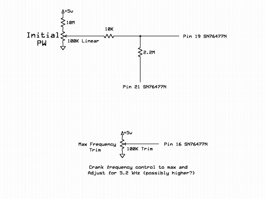
My first attempt was this:
 |
I sent Thomas the above schematic with the following text:
I'm just running 5V through a 10M resistor to a 100K pot, and that 100K potis used to dish out the voltage to Pin 19 through a 10K resistor, while attenuating and feeding the LFO into it through another high value resistor.
Now, without the 2.2M resistor hooked up (IE, if a switch is put in that disconnects it), this 100K pot varies the fixed PW smoothly throughout the range of the pot - it's a manual PW control!!
Switching in the 2.2M resistor, which is connected to pin 21, allows a small fraction of the LFO current into the circuit - enough to modulate the PW throughout its range. In this mode, the PW control acts as an initial PW control. Setting it to the middle allows a smooth PWM to take place. Adjusting it to either side gives it more of a non-linear modulation.
The second part of the schematic is used to set the max frequency of the circuit (this is a trimpot, but probably could be replaced with a couple of resistors if everything ends up working all right). For the time being, I have mine set so that if I crank up the manual frequency control to max, the frequency is 5.2 kHz. I have yet to experiment with how far we can push this voltage (I.E. how low can we go).
After sending that message, I went back to the breadboard. Not satisfied with the pot's action, I tried yet another approach, which I sent to Thomas:
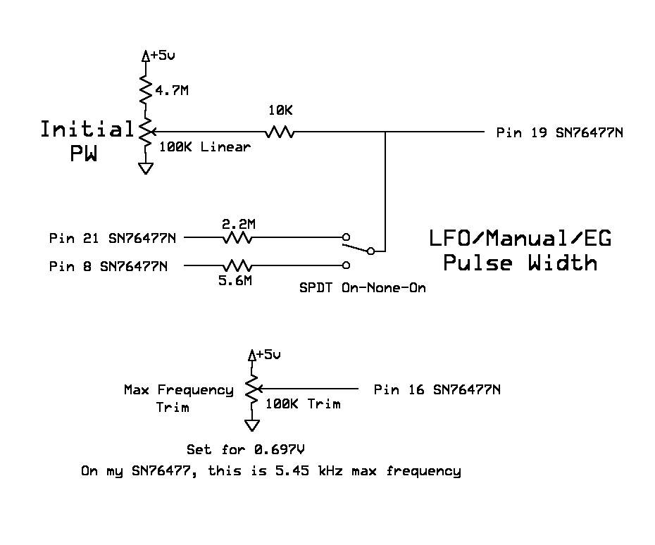 |
I tweaked the values a little - I replaced the 10M resistor with a 4.7M (actually, I used 4.75M - that value happened to be lying there and I couldn't off-hand find my 4.7M resistors). This gave a wider range of PWM value.
I coupled in the EG with a 5.6M resistor - that seems to work pretty good - it gives a nice little 'blat' on the attack =-D.
I tuned the high freq up just a tad (5.45 kHz), and I also measured the voltage pin 16 was at with the tuning - 0.69V or so. Going up much higher than that really starts to narrow the range on the PW control.
The PW control actually works for a really smooth LFO all the way CCW (as it's wired into my breadboard). Most effect of the EG is also with the PW control set full CCW. IIRC, widest PW was full CW.
Well, if it works it works, if it doesn't, it doesn't.
The PWM worked, but the whole thing turned out to have an ill effect on the tuning, and limited the top end a bit more than Thomas cared for. So, I figured, that was that - no PWM.
A few days later, Tom emailed me - apparently the bug I'd planted in his ear wouldn't leave him alone. He'd found a solution for PWM - he'd worked through it and wound up with quite an eloquent balance of pulse width modulation and high end - the top end still goes up to a very respectable 7.5 kHz, and he was able to attain the timbral variety of pulse width modulation. He discovered the key to the problem was that the PWM input had a very high input impedance. The design he came up with is essentially what is found in the SN-Voice today. Except for one thing....
A day or so later, Thomas found VCO high end and accuracy were not the only hoops to jump through regarding pulse width modulation. We'd decided to make control of the pulse width modulation under either EG or LFO control, with the selection switch having an extra position to render a fixed 20% duty cycle.
The first go around had a greater range of PWM (around 50% to 20% - the PWM range of the SN76477 isn't all that wide to begin with). However, the R52, R62 and R63 values chosen for that range loaded the EG down and altered the frequency of the LFO when PWM was switched to either function. Going back to the drawing board rendered the more stable values found in the design, with more of a 40% to 20% sweep - enough for a nice chorus-like animation. Plus, the new values had the extra benefit of allowing the more useful setting of fixed 50% duty cycle square wave rather than fixed 20% duty cycle pulse wave.
The Digital Noise Clock
The digital noise clock is another interesting landmark in this design. Before Thomas started this project, he was finishing up a different design. Remember the SuperController, the SN76477 based control module mentioned elsewhere on this site? Thomas has perfected a greatly enhanced version of it - but this new version of the SuperController does not use an SN76477. The reason this is mentioned is that the noise clock of the SN-Voice is a somewhat scaled down version of a clock found in his new SuperController design.
Notice the clock is fed with an expo converter made up of two 2N3904 transistors. That's right - this clock is an exponentially controlled circuit that drives the internal pseudo-random shift register of the SN76477. This means that it responds very well to keyboard control (sort of like turning your keyboard into a drumpad with the right patch set up). In fact, this circuit works so well, it runs quite fast enough to expose the "chug-chug" pseudorandom repeat of the SN76477's digital noise generator (the souped up version in the new SuperController has a much longer pseudorandom chain and does not display this tendency). Still, if you want nice intense noise sweeps or short drum- or steam-like bursts, this circuit fits the bill. As a side-note, the accuracy of this expo converter is not terribly critical - it delivers the desired exponential response without resorting to matching of transistors.
Of course, having that CD4046 sitting there with its unused internal XOR gate provided another opportunity, which leads us to......
The Envelope Generator
The EG configuration we started out was a one-shot AD circuit, which is the application the data sheet seems to hammer on the most. In order to obtain this response, a trigger is applied to Pin 9 System Enable. After the trigger is received, the attack rises to maximum EG level at the rate of the attack pot, and the decay falls back to 0V at the rate determined by the decay pot.
Thomas had added an additional 'Width' pot to make the EG more versatile. This entailed placing a 10 uF cap at Pin 23 One -Shot Control Capacitor Input and a 1M pot in series with the resistor at Pin 24 One-Shot Control Resistor Input. The setting of the Width pot would place a sort of 'hold' at peak sustain between the attack and decay cycles of the EG. This worked OK, though we both found it a bit unwieldy. Moreover, we both noticed a 'twitch' in the VCO frequency when the one shot capacitor hit the point where the width portion of the EG expired.
I set about trying to solve the frequency twitch problem and quickly realized that, once a trigger was received at pin 9, holding pin 23 low would allow infinite sustain. Sure enough, checking the datasheet, it did mention, after the usual rigamarole about the one-shot capacitor, that the cap could be eliminated and the cycle could be ended by bringing pin 23 high.
At this point, Thomas had added the CD4046 digital noise clock, and had configured its internal EXOR gate as an inverting buffer to handle the trigger signal, thus eliminating a transistor and its associated components. I got the bright idea to rig the EXOR as a noninverting buffer, remove the input capacitor from the trigger circuit, and take the inverted gate signal at the transistor's collector straight to pin 23 - thus bringing it low. I then put Thomas' original trigger circuit back in to trigger pin 9, and voila! - it worked.
I excitedly sent this to Thomas, and he replied that it would work, but with a lot less effort (and quantity of parts) than the circuitry I resorted to. He simply left the EXOR as he had it, moved the input capacitor to the collector, and tied the other end of the capacitor high to +5V with a 100K resistor. He left the EXOR processed trigger with the same path, and ran the inverted gate present on the collector of the transistor to pin 23 through a 100K resistor.
It worked like a charm, simply by adding two resistors and changing the routing ever so slightly (this eliminated the two transistors and the not insignificant number of other components of my method). I couldn't help but mention to Thomas that, perhaps one day, someone in the transistor industry may decide to put a stop to him.....