
The VCO-1 Project
An Uncomplicated VCO That Truly Delivers
Preface: Towards the end of May, 2007 I began to grow excited over the possibilities the summer of 2007 might hold. Through fall, winter and spring, Thomas Henry pursues his career of teaching mathematics in Mankato, Minnesota, but during the brief respite he has from that over the summer, he always manages to unleash some new design that has been tickling his imagination throughout the school year. In the summer of 2006, Thomas developed the XR VCO, the SN-Voice, the UD-1 Drum Voice, then nonchanlantly capped off the season with a design *for an entire synthesizer* that contained two different VCOs, a phase shifter, a VCA, a multi-mode filter, a very unique LFO (which would occupy many pages ot text just to describe all of its uses), a sample and hold, a power supply, and a digital noise circuit, the specifications of which are quite astounding. This collection of schematics turned into the publication "An Analog Synthesizer for the 21st Century" which is available from Magic Smoke Electronics.
So, I was not terribly surprised (but very pleased) when Thomas contacted me about a design he wished to make freely available to the public. He sent me the schematic, and I was amazed to see what appeared to be a very simple little VCO circuit. I breadboarded the circuit, following Thomas' schematic to a 'T', except I didn't have a 2K tempco on hand, and instead of 2 2N3906 transistors, I used a 2SA798 dual transistor. I found within the "simplicity" of the design a very sophisticated Voltage Controlled Oscillator. I also discovered that this little VCO was a virtual powerhouse - I told Thomas later I felt like Isao Tomita playing that circuit I had on the breadboard. It's stable, responsive, very accurate and sounds absolutely marvelous - especially through the Mankato filter Thomas designed a few summers back. I was literally bowled over with how well it worked and how *good* it sounded. Perhaps a VCO is just a VCO, but I certainly felt inspired playing this one.
Sound Samples
In fact, before we get started with Thomas' treatise on this fabulous little VCO, let's have a preview of what it actually sounds like - I believe this helps put everything in perspective.
We'll start with a sample Thomas Henry provided, demonstrating the VCO-1 under MIDI control. Thomas points out each waveform as it's presented. This sample certainly demonstrates the pitch accuracy of the VCO-1!
This next sample again was provided by Thomas. It was originally recorded to demonstrate the MTS100 MIDI to CV Convertor that Thomas marketed back in the days of Midwest Analog. Where the previous sample hints at the pitch accuracy of the VCO-1, this sample absolutely confirms it - listen to this "homebrew" VCO play right along with a crystal oscillator controlled Casio CZ-1000.
This final sample is one that I recorded shortly after breadboarding the VCO-1. The setup for this sample is quite simple: The PWM output of the VCO-1 is sent through my breadboarded Thomas Henry Mankato filter, through reverb and then into my Korg D8 recorder. I'm using my Thomas Henry keyboard to control the VCO and filter frequencies. The pulse width modulation is provided by a Ray Wilson LFO, and there is occasionaly some FM vibrato provided by a second Ray Wilson LFO. The envelope generator used on the filter is a Ray Wilson ADSR envelope generator.
At the time this sample was recorded, I think I'd spent all of three minutes calibrating the VCO. The breadboarded Mankato has been on breadboard since summer 2004 - it's a relic of the days I was beta testing the filter for Thomas.
I don't think anything says analog any better than the VCO-1 through the Mankato.
I've created a resource page containing links to technical references, parts procurement information, and sound samples. Thomas' article, contained below on this page, makes use of the schematics, PCB and parts layout, and panel examples. These files are placed as links in the appropriate sections of the article. The resources page has a "one stop download" section that has all of these documents in one place for easy downloading. Be sure to check out the samples Thomas provided, demonstrating the pitch accuracy and stability of the VCO-1!!
So, without further ado, here are the circuit, schematics, layout and explanation of the VCO and theory behind it in Thomas' own words.
Voltage Controlled Oscillator: VCO-1
By Thomas Henry
VCOs can get pretty complicated in a hurry. If a person starts demanding all sorts of bells and whistles, the circuit and front panel could grow by leaps and bounds. But, these are mostly doo-dad features, things that really aren't needed all that often. The approach taken in this project is in the opposite direction. Instead of frills, we'll concentrate on stable, steadfast performance; in fact we can arrive at a very usable nine octave range without much trouble at all. I've dubbed this project the VCO-1 since it makes a terrific first oscillator. It may not have all the glitter the big guys do, but on the other hand it is a reliable workhorse. Let's look a little more closely.
Design Analysis: The Exponential Converter
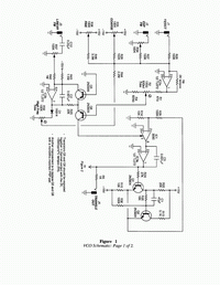
The schematics have been spread over two pages, as shown in Figures 1 and 2. In rough terms, the first page focuses on the exponential current source, while the second is concerned with waveform shaping.
 |
The line we'll take here is to add an exponential voltage-to-current converter to the trusty old Schmitt trigger-integrator triangle oscillator. A 3080 operational transconductance amplifier (OTA) is used as a controllable resistor to modulate the flow of current to the integrator. But we're getting ahead of ourselves, so let's back up and examine the converter first.
Refer to Figure 1. Depending on your age and background, you may or may not recognize the Q5/Q6 transistor pair topology. This design has been knocking around for ages, back to the 1970s at least. Over the years the circuit has proven to be quite popular, having been slightly modified and simplified by others (including me). See the sidebar to the right for a bit of its history.
IC2a forms the control voltage summer. I've shown the circuit with a variety of inputs: a 1V/octave input for keyboard, an attenuated exponential FM input, a coarse control and a fine control. You'll note that R46 is a very large 3.3M, which is why the fine control has less of an effect than the coarse pot.
The op-amp and related components scale the control voltage appropriately. With the values shown, it's possible to tweak trimmer R2 to get a good 1V/octave response. By the way, for idealized parts, the tap of voltage divider R1/R2/R4 calculates to be 50W/450W which puts trimmer R2's wiper near the center of its rotation.
The actual exponential conversion is handled by the pair of PNP transistors, Q5 and Q6, mentioned above. Without getting into all of the gory details, the general idea is that the collector current of a transistor is exponentially related to the input base-emitter voltage. Unfortunately, something called the emitter saturation current creates a deadly temperature sensitivity and could easily cause the unit to go way flat or sharp as things warm up or cool down-hence the second transistor, Q5 in this case. Because of the way it's been configured, the error current within Q5 moves in the opposite direction. If the two semiconductors are closely matched in performance, then most of the temperature dependence is canceled out. Obviously a high quality pair makes a difference, and also the mechanical bonding. If you can locate a monolithic matched PNP pair, then by all means use it for superior results. On the other hand, I have had good luck simply cementing two 2N3906 transistors together with epoxy. IC2b and associated components form the current reference for the converter. Assuming a 15V power supply, its value, IREF is set by:
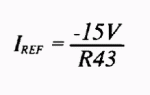
Theoretically you select this number to represent the center of the desired current range pumped into pin 5 of the 3080 (which occurs when the input voltage is 0V). However, realizing that small currents can be involved, this is often bumped up a bit; after all, we're using real op-amps and transistors, not idealized ones. For resistor R43 = 1.5M as shown in Figure 1, IREF is 10uA and that seems about right-not too big, yet not too small. However, feel free to experiment with this value if you think a different reference current might improve things. Resistor R23 sets the maximum current that the source can output. This quantity is given by:
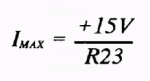
For R23 = 22K as shown, we get a maximum current of 0.68mA, well within the limits of what makes the 3080 happy. By the way, most designers typically push this a bit for VCO circuits using an OTA, just to get a little extra range. But again, feel free to experiment with R23, keeping in mind that the max control current expected by IC1 should never really exceed 1mA to avoid thermal runaway problems. The nice thing about the topology of this current source is that a linear modulation input comes along for free; a voltage is simply injected into the current reference via R42. C12 blocks any DC component, and thus a deviation from a center frequency is easily achieved. This is excellent for providing vibrato, or in the creation of clangorous sounds. By the way, C2 is included simply to keep the current reference from oscillating spuriously.
There is a remaining temperature dependence introduced by the scaling circuitry. Fortunately this is a first order quantity and easily dealt with. Note resistor R8 in the feedback loop of IC2a. It's actually a +3500ppm/Co 2K thermistor, sometimes called a "tempco" for short. Its duty is to cancel out any remaining temperature dependence in the scale factor. To really cinch up the stability of the VCO-1, Q5, Q6 and R8 should be expoxied together so that they all ride at the same temperature.
Analog synth VCOs can go slightly flat on the high end, due to two reasons. First, there is something called the bulk emitter resistance, a characteristic of the conversion transistors used. And then there is the possibility of reset time errors; this is a property of the Schmitt trigger which figures in the actual oscillator stage of the circuit. Both effects can usually be minimized with high frequency trim R32. Notice the clever way this handled. A portion of IC2b is tapped and fed back around to the control voltage summer. But mistracking typically only occurs on the high end, when the control voltage rises above a certain point. So, the output of IC2b must overcome the inherent drop of diode D1 (0.6V or so) before it can contribute anything. You will notice further that R44 is quite large at 2.2M; the amount of correction required is very tiny, indeed.
That's all we need to know about the exponential converter, so let's turn our attention to the oscillator proper, still referring to Figure 1. IC3a is configured as the integrator mentioned earlier, with capacitor C3 setting the basic operating frequency. When building the circuit, you'll get best results if you make C3 a polystyrene type, which is fairly stable with respect to temperature.
Preceding the integrator, however, is IC1, the 3080 OTA. As alluded to, it's behaving as a variable resistor, determining the amount of current flowing into the integrator. The output of the integrator (IC3a) is tapped for its triangle wave. R5 sets the output impedance to the industry standard 1K. Due to the trip points of the Schmitt trigger (coming next), the triangle wave is 10Vpp (+/-5V), another standard deemed desirable.
IC3a also presents the triangle wave to the input of the Schmitt trigger; this is a discrete version built around transistors Q1 and Q2. I haven't taken this approach just to be a penny-pincher (and there's no doubt the transistor method is dirt cheap), but rather because I found I needed as much speed as possible. The various op-amps I tried as Schmitt triggers just didn't switch quickly or cleanly enough at higher frequencies. This isn't a trivial matter either, for as hinted at earlier, a lag in the switching time manifests itself in noticeable tuning imperfections and variability in the output amplitude of the triangle. In a nutshell, the discrete Schmitt trigger is about as good as they come, even if it does seem to be out of the stone age. Incidentally, I first saw this transistor application in "Improving the Linear VCO", Application Note Number 20, December 25, 1976, by the incredibly prolific Bernie Hutchins of Electronotes fame. It recently made a reappearance in the December 2003 issue of Nuts & Volts Magazine (p. 64). It's a technique that deserves to be better known.
Determining resistor values for it turns into an interesting number game. To set trip points of +/-5V, R22 should be double the value of R15, and R15 should be double that of R13. And if it isn't clear, the output of the Schmitt trigger is tapped at the tied emitters of Q1 and Q2. In fact, you could grab a +/-5V square wave here, as long as you buffer it. However, it's generally more useful to send the triangle wave (which already is buffered) to a comparator and derive a square wave from it. Moreover, in this way pulse width modulation comes along for free.
C1 is a speed-up capacitor; its duty is to drain away any accumulated charge from the base of Q2. This permits the transistor to change states more rapidly. I've shown a value of 47pF, but you may want to experiment a bit, since it does depend upon the particular transistor used, as well as your construction method. It is entirely possible that a handwired circuit, for example, may not need the cap at all because of stray capacitance elsewhere.
Finally, the output of the Schmitt trigger is fed back around to the 3080 posing as a controllable resistor. When the trigger goes high, C3 begins to charge at a rate determined by the OTA. When the trigger goes low, the current reverses and the cap discharges.
Design Analysis: Waveform Circuitry
We've already seen that the triangle output at J4 is buffered and has the desired output impedance and voltage level. Let's turn our attention to the other waveforms possible with the VCO-1. Consider the sine wave first.
There are essentially two non-reactive ways to convert a triangle wave to a sine wave: stepwise linear approximations and non-linear transform circuits. I've never liked the former method, considering it just too awkward and complicated for the "stick-like" results it offers. (Stepwise linear approximations are used in some of the older PAiA synthesizer modules and in the 8038 VCO chip, though). With regard to the latter method of non-linear circuits, I've played with many approaches over the past quarter century. Some exploit the characteristics of FET transistors, while others go for a full chip design. But in my estimation, the most efficient method is that utilizing a couple of discrete transistors wired as a differential pair. The idea dates back almost 40 years, when the article "Non-Reactive Filter Converts Triangle Waves to Sines" appeared in Electronics, March 8, 1965; the authors were R. D. Middlebrook and F. Richer. This approach really caught on and by the late seventies, versions of it showed up in all sorts of commercial and homebrew synth gear.
With the ready availability and low price of integrated circuits, later designers set out to "improve" the idea by utilizing the differential pair within the 3080 transconductance op-amp, mimicking the original concept. But in some ways this is overkill. I believe the earlier discrete version sounds great, and is simpler and cheaper to build. It's good for distortion levels around 1% or 2%, more than adequate for music-making.
The mathematics of how the circuit works is fascinating, but beyond the scope of this handbook. For now, we'll skip over the calculations and instead concentrate on the practical details. As I mentioned earlier, I've been playing with the differential pair notion for many years and have arrived at some component values that really give superior results.
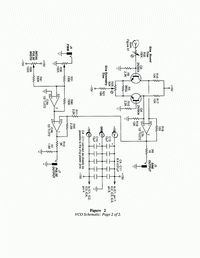 |
Refer to Figure 2 now. Recall that we've already sized up the triangle wave to be 10Vpp. This happens to be the correct value needed by the input of the triangle-to-sine converter. We'll tap into it and apply it to the base of Q3, which along with Q4 forms a differential pair. We deliberately overdrive the base of this transistor forcing it into its nonlinear region. The funny thing is, when overdriven like this, the resulting signal uncannily begins to approximate a sine wave. Trimmer R33 is used to adjust the "roundness" of the resulting approximation. Tweak it in one direction and the wave gets pointy like the original triangle; go too far in the other direction and it flattens out like a rectangle. But when you hit the sweet spot in between, the output indeed curves in a pleasant manner and assumes its new guise as a sine impostor.
The second trimmer, R21, let's you adjust the symmetry of the approximation. Go too far to the left and the output will be skinny and pointed on one side while squat on the other. Spin R21 the other way, and the reverse happens. At the correct setting, however, you'll get a neat, symmetrical waveform. In terms of what your ears can hear, at one extreme or the other you'll detect some extraneous harmonics giving a more brittle sound. At the correct setting, though, you'll hear a pure, flute-like tone.
Moving on, the outputs are tapped at the two collectors and fed to op-amp IC3b, which is configured as a differential amplifier. With the values of all the resistors as shown, the sine approximation appearing at J5 is a nominal 10Vpp, with a 1K output impedance. If you'd like to adjust the output amplitude one way or another, simply alter R18 and R19. To maintain a DC center-line of 0V, these two must be balanced and so should be changed by an identical amount. A larger value gives a heftier output and a smaller value yields a lesser one.
Generating pulse width modulation is a piece of cake as we'll see next. At the heart of the action is op-amp IC4b which is configured as a comparator. The 10Vpp sine wave is fed into the non-inverting input by means of resistor R11. The instantaneous level of the sine is "compared" to a fixed DC voltage applied to pin 2. If the level is higher, then the output at pin 1 jumps to near +15V. If lower, then it goes to -15V. R45 provides a smattering of positive feedback, forcing the output to snap faster and more cleanly than it would otherwise. Voltage divider R12/R7 chops the output down to the usual 10Vpp level, while simultaneously providing a 1K impedance. You'll typically want to modulate the pulse width with an LFO, envelope generator or some other control voltage source. IC4a sums a PWM (pulse width modulation) input from J6 with some fixed offset provided by R39. By playing with controls R38 and R39 it is possible to achieve 0% to 100% control over the width of the output rectangular wave.
Building it
Most of the parts for this project are easy to come by. R8, the temperature compensating thermistor, is perhaps a bit harder to find. As mentioned above, C3, which is the tuning capacitor for the VCO-1, should be polystyrene for maximum stability. Recall that a VCO is the single most important module in the synthesizer and that the human ear is very sensitive to fluctuations in pitch. It follows that the tuning element (C3) should be as stable as possible and polystyrene is ideally suited. And in general, use the highest quality parts throughout. While not strictly necessary, R2 (the 1V/octave adjustment) could be a multiturn trim pot. This eases the task of tuning somewhat and allows for very precise adjustment. However, for most musical applications this isn't necessary. Just use a good quality trimmer and you shouldn't go wrong. Finally, IC sockets take away the worry of cooking things when soldering and also makes troubleshooting less of a hassle if needed.
Construction of the VCO is best accomplished with printed circuit board techniques, although other methods may be used as long as "rat's nest" wiring is avoided. An exponential converter is a rather sensitive device and a mass of tangled wires coming and going from it can often create stray capacitance problems. Other than this precaution, there is nothing especially critical about the construction of the VCO-1. Figure 3 shows the printed circuit board artwork, while Figure 4 gives the parts placement guide.
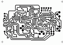 | 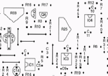 |
Figure 3: PCB Artwork | Figure 4: Parts Placement Guide |
Here are several things to note. First, there are seven jumpers to install, the price you pay for a single sided printed circuit board; you can use left-over snippits of resistor leads for these. Further observe that C12 mounts behind the front panel connecting J3 to R37. Be sure to observe the orientation of the transistors. Figure 4 also illustrates how Q5, Q6 and R8 are mounted in contact with each other for temperature stability. If using individual transistors, connect them up with a dot of epoxy cement.
The pads which connect to the panel controls are indicated with slightly larger dots. Each is labeled with the item it connects to (e.g., J1, R34, etc.). Read the parts placement guide side-by-side with the schematics and you shouldn't have too much trouble interpreting things.
Notice that there are pairs of pads for each of the power supply connections (+15V, -15V and GND). This is so you'll have a duplicate in each case to run to the front panel controls. And naturally, ground connects to the panel in one place only to prevent hum inducing ground loop problems.
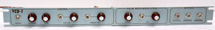
Make an attractive panel, and if possible apply graphic techniques to it. For example, below the output jacks, draw pictures of the various waveforms (sine, triangle, pulse, etc.). Pictures are always easer to interpret than words. Figure 5 shows a suggested panel design, while Figure 6 gives the associated drilling guide.
 | 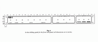 |
Figure 5: Panel Design | Figure 6: Panel Drilling Guide |
But besides making the panel attractive, take pride in your wiring and use tie bands, clamps or whatever is required to dress the connections neatly. Chances are the circuit will work like a champ right off the bat if do things in a tidy and orderly fashion.
Calibration and Adjustments
Tweaking the module isn't all that hard, but it does take patience. Let's start by tuning the VCO-1 for a 1V/octave response. There are a number of ways to accomplish this, and each system requires varying amounts of test equipment. For example, you could tune it with a function generator and oscilloscope using Lissajous figures, or with a frequency counter and digital voltmeter. However, the simplest (and in many ways the best) way is to simply tune it with your own ears. After all, if you can't hear that anything's wrong, then nothing is wrong! Here goes.
Plug the keyboard control voltage into the 1V/octave input at J1. Then hook up an amplifier and speaker to the triangle wave output and adjust R35 and R36 until you hear a tone. Now repeatedly play a middle C and the C one octave above this, back and forth. Adjust R2 until you hear an exact octave interval. That's all there is to it!
Now try out all of the keys; do you hear a good equally tempered scale up and down the whole keyboard? If you do, then you can skip monkeying around with R32 (and this will probably be the case). Otherwise, if the high end sounds a little flat, adjust R32 somewhat. The purpose of this trim is to boost the frequency of the very high range of the VCO, since that's usually where irregularities occur. After adjusting the trim pots, dab a little fingernail polish on each to hold them in place.
To wrap things up, adjust the sine trims for minimum distortion. One approach is to connect the sine output to an oscilloscope. Tune the frequency to about 1kHz for easy viewing. Now simply tweak the trimmers (R25 and R33), one after another for the best looking waveform. This will require several passes "around the horn" to get both of the pots to their optimal positions. An even better method is to connect the output to an audio amplifier and let your hearing do all of the work. Believe it or not, even the untrained ear can perceive an extremely tiny amount of distortion. Watch the output level, however. Remember this is a hot circuit and you won't want to blow up your ears or your loudspeakers. Again, tweak the pots until no overtones or harmonics are obvious. Of course, you could always use an harmonic distortion analyzer, but who has one of these lying around? Anyway, your ears (and the ears of your audience) are the final arbiters, so why not give them the job!
Using the VCO
Despite its apparent simplicity, there's a lot of subtlety to the VCO-1. Really take your time in getting familiar with it. Learn to make the most of its features and you'll soon have many new and unusual sounds underway.
There are a fair amount of controls, so if you're having trouble when you first fire up the unit, make certain that you've accounted for the effects of all of the knobs. For example, if you're not hearing any sound at all, check to see if R35, the coarse tuning control, is in the audible range. The VCO-1 oscillates all the way from the subaudible to the supersonic, so be sure that you've got it in a realm you can hear. Another case where you might not hear anything is when the pulse width control is set such that the duty cycle is 0%. A zero-percent duty cycle means no frequency is present at all! Adjust R39 slightly and you should hear some sound again. Try out all of the outputs and confirm that they work. Then listen critically to the various timbres that these waveforms create. Notice how the sine wave is very pure while the pulse wave is harsh. with the triangle wave somewhere in between.
Finally, give vibrato a whirl if you've got an LFO handy. You will probably want to use the linear FM input for this at J3, but feel free to try the exponential input as well. Note how linear FM limits you to a maximum of about one octave deviation, while the exponential input permits around a dozen octaves. These are just suggestions to get you started. You will find this to be a very versatile VCO, but to really get the best sounds from it, be sure to set aside enough time to practice. Like any musical instrument, you must be prepared to commit to fair amount of rehearsal.