
The XR-VCO Project
A Unique Voltage Controlled Oscillator
In June 2006, Thomas Henry sent me an email asking if I wanted to breadboard a VCO he was working on. I'd breadboarded some circuits as he developed them back in the summer of 2004. It was a blast doing this - years ago Thomas' book "Build a Better Music Synthesizer" was the thing that opened my eyes to the fact that a synthesizer could be built totally from scratch in one's own home, and this was truly a wonderful chance to watch him breathe life into some new designs. One of these designs was the outstanding Mankato filter, soon to be offered by Magic Smoke - I've still got the second one ever breadboarded on my breadboard, and it *still* sounds wonderful. So when Thomas made the offer of breadboarding the VCO, I jumped at the chance.
Thomas had but a small window of opportunity to do something, in between when the semester ended and when he had to pick up once again with his teaching duties, so for a couple of weeks, there was a fast flurry of activity - the original design, the addition of voltage controlled skew, selection of op amps, and the last phase, seeing how far we could push a function generator IC to perform in a musical manner. Of course by we, I mean Thomas would design, send me the schematic, and we'd work in parallel to see if the results matched.
Enough about that, here's the skinny on the VCO itself:
We were able to get five musically useful octaves out of it - by that I mean that it will respond to a V/Octave input in tune throughout those octaves. It would be much better, but we 'hit the wall' on what the XR-2206 could provide. The part where it fell out of cohesion was at the very low end. Below is a link to a table of the best results Thomas was able to glean out of it:
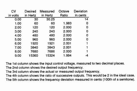 |
As one can see, the octave between 60 Hz and 30 Hz fell out quite a ways with the upper octaves. It's possible to tune it for an average of these values and get five good octaves out of it.
Features
The good stuff: it's a simple circuit, with a lot of bang for the buck/parts count. Thomas really wrung out the chip to get a good feature set for the VCO. The features include:
- V/Oct Input
- Coarse Tune
- Fine Tune
- Expo FM Input
- Linear FM Input
- Sync Input
- Pulse Output
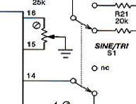
- Switchable Tri/Ramp or Sine/Rampoid output
- Voltage Controlled Skew
One may wonder at that last feature - what is the skew function? Skew provides a method to morph from either a triangle wave to a ramp wave or a sine wave to a 'rampoid' output. Here's the cool thing - it not only morphs the wave shape, but the ramp or rampoid output is at exactly *twice* the frequency of the triangle or sine wave. The effect is an awesome function - putting it under voltage control is quite an experience (it can sound quite filter-like even without a filter). Even at static settings, it can be somewhat like dialing in a sub-oscillator, only, as with most sub-oscillators, the lower frequency is not a pulse wave, but rather a triangle or a sine wave. It really gives some 'bottom' to the sound.
To get a really good idea exactly what the skew function does, click the link below for some scope shots of the skew in action!
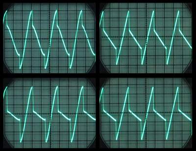 |
Sound Samples
Below is a link to a sound sample of the skew in action. This sample has the XR VCO sine output going through my discrete Rene Schmitz 2040 Filter clone, through a Ray Wilson VCA and on out, with a touch of spring reverb. The skew is modulated by a triangle LFO, while an EG and additional LFO is controlling the Filter. Another EG is controlling the VCA. The VCO and filter are also controlled by my Thomas Henry keyboard. The Skew can be plainly heard shifting the VCO into a higher harmonic register and back down.
Thomas Henry sent the following four samples along. They demonstrate the skew function and the sync quite well. All four samples are using the sine output. No filter or any other modulation, other than what is mentioned, was used.
This first sample is a manual sweep of the skew function from sine to octave-up ramp and back.
This next sample puts the skew under envelope control.
The following sample demonstrates the sync function, with no skew involved.
This final sample from Thomas demonstrates the effect of skewing the VCO while it's synced.
Schematics
Note: A small error has been spotted on the schematic. Fortunately, it's not a big one nor is it like to cause anyone any problems if they've already put the circuit together. It concerns diode D2 in the VC Skew summer. Here's the fix. Break the connection of D2's anode and reconnect it to the output of the op-amp at pin 1. In other words, D2 straddles pins 2 and 1 of the op-amp now.
With the arrangement as it currently is in the schematic, the only time anyone would notice something funny is if he or she was pumping in a negative control voltage. No harm would ensue, but the skew response would wrap around, which might be surprising. Anyone who's etched the PCB will have to cut a trace and put in a kluge. This is easy to do, since there's only the anode of D2 to alter.
 |  |  |
XR-VCO Schematics Page 1 | XR-VCO Schematics Page 2 | XR-VCO Parts List |
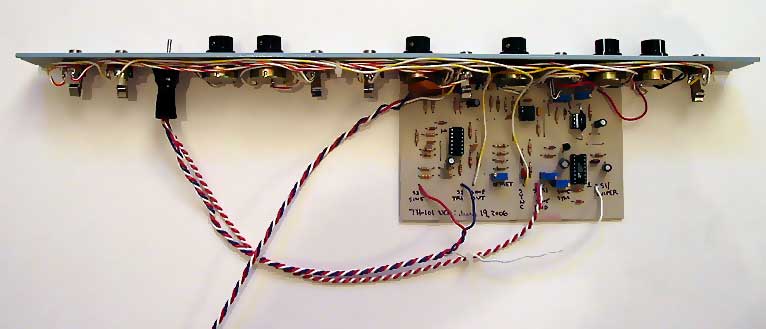
PCB and Parts Placement
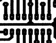 |  |  |
XR-VCO PCB | XR-VCO Parts Layout | XR-VCO Panel |
Construction Notes
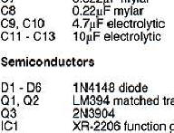
The LF442 is recommended as the opamp to use for IC2. We tried a few different op amps, LM1458, LF442, TL072 and TL052, with the LF442 giving the best performance. In fact, the TL072 worked abysmally and should not be considered a candidate. The TL052 fared a bit better than the TL072, but tended to act quite squirrely at certain frequencies (heavy oscillation of the VCO output) and should not be considered as well. The LM1458 works 'OK', but does not possess the superior specifications of the LF442 and will not be nearly as accurate. Other op amps other than those mentioned may or may not work - we just never tried them.
Ian Fritz suggested on the Synth DIY list that a TL072 may work there if a 1n cap were placed across the 2K tempco in the CV summer of the expo circuit - that is certainly something to try and we think it very well may work - I haven't tested it yet.
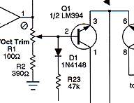
For temperature stability, a 2K 3500 ppm resistor is required to be in direct contact with the LM394. If you do not care about temperature stability (your use can tolerate frequency and scale variation with temperature) a 2K metal resistor will work fine there.
Calibration
After your build is finished, and you're ready to try it out for the first time, connect an oscilloscope to pulse output and try adjusting the coarse control - you should see a very wide frequency response as you twist the coarse control. If you do not have an oscilloscope, hook it up to a mixer or an amplifer but first make sure you have the volume down as low as possible or attenuate the signal greatly! The outputs of this VCO are 10 volts peak to peak!
Once you've established you have oscillation by observing the pulse output, there are three items that must be calibrated:
- The Sine/Tri Offset
- The Sine Shape
- The V/Oct Response
To calibrate the Sine/Tri output, set the sine/triangle output switch to 'triangle'. Observe the triangle output on an oscilloscope and adjust the Offset Trim (R24, single turn 50K trimpot) so that the triangle wave is centered around 0V.
Next, calibrate the Sine Shape. Set the sine/triangle output switch to 'sine'. Calibrate the sine shape by alternating between the Sine Symmetry Trim (R22 25K single turn trimpot) and the Sine Round trim (R3 500R single turn trimpot). You can do this by observing the waveform on an oscilloscope, or you can use your ears. You will be surprised at how accurately your ears can tune a sinewave - just adjust the pots until you detect as much of an absence of harmonics as possible.
Note that if you find that the sinewave is a tad lower in amplitude than the triangle wave, you can up the value of R21 to 22K or so. My sinewave was maybe a volt lower than the triangle wave, while Thomas' breadboard had it perfectly at 10V peak to peak. There appears to be enough variation between XR2206 IC's that this can happen. Thomas suggested I raise my R21 to 22K, and that brought it in perfectly. Having said that, there was no discernible difference in amplitude (ears are terrible amplitude detectors on a linear scale), so I'm not sure if it's terribly worth worrying over.
The V/Oct calibration is performed using the V/Oct trimpot R1 (100R trimpot, multi-turn) and the High Frequency (HF) Trim R42 (1M trimpot, multi-turn). Make sure you start out with the HF trim maxed out at 1MOhm. You will need an accurate voltage source that can be set in steps of 1V (CV keyboard, CV to MIDI converter, etc.) and either an oscilloscope, frequency counter, or a tuned keyboard that you can match by ear (the ear being the most sensitive piece of equipment most people have anyway).
Start calibrating at 60 Hz on up. Resist the tendency to adjust the HF trimpot until around 7 kHz. Move up and down between two notes one octave (1V) apart to set the right interval for that first octave. Then move between the initial octave and the next octave. If you're anything like me, this will take many trips "round the horn". Once you've got that tuned, check the lower octave down around 30 Hz.
Of course, you can start at any point - generally starting higher will make this VCO more accurate at the high end, sacrificing tuning at the low end. Starting lower will limit the accuracy of the VCO throughout the range, but not to the extent it becomes unpleasant - this sacrifices range, but makes the all-important lower octaves a bit more palatable. Experiment. Once you get the hang of it, you'll get a good feel for the response you prefer. Trust me, if I can tune this thing, anybody can (I'm the world's worst VCO tuner).
Operation
Now that you've got this puppy together, and tuned up, it's time to have some fun with it. Generally, it operates like any other VCO.
Plug a V/Oct input source into the 1V/Oct input to control pitch.
Plug a modulation source into the Expo Modulation input to modulate the pitch in an exponential fashion (great for vibrato and audio frequency effects). The attenuator, R32, will control how intense the effect will be.
Plug a modulation source into the Linear Modulation input to modulate the pitch in a linear fashion - great for audio frequency modulation as well. Note this input is AC coupled and will only accept AC inputs. Again, the associated attenuator, R35, will control the amount of modulation applied.
Plug a 10Vp-p square wave from a second VCO into the sync input to achieve sychronized VCO effects - generally, the 'Master' VCO in this configuration will be tuned to a lower pitch than the XR VCO.
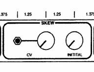
Plug a control voltage into the Skew CV input to control the skew of the triangle/sine wave. The intial amount of skew can be set manually with the "Initial" control. A more negative value of CV will skew the waveform towards the sine or triangle wave (whichever is selected by the Sine/Triangle switch, and a more positive value of control voltage will skew the waveform towards the ramp/rampoid waveform. The Skew attenuator will allow you to adjust how much the CV affects the skew. Try different CV sources - LFOs, EGs, random generators, keyboard voltage, VCOs, pitch bend controller(!); whatever strikes your fancy. The skew will go from one extreme to the other with a 5V input, but the controls are set up so that you will have enough range to use higher voltages, inverted voltages and so forth. And don't forget about the Initial skew control - it works great for setting a 'static' timbre as well.
Plug into the Pulse output to get a pulse waveform. Plug into the 'Triangle/Sine' input and set the Triangle/Sine switch to the desired waveform. With the Initial skew control CCW, you will get a triangle or sine wave (as determined by the Triangle/Sine switch). Rotating the Initial skew control, or applying a positive voltage to the Skew CV input will skew the output to the ramp or rampoid waveform - at one octave up. The effect is like introducing higher harmonics into the signal.
Finding Parts
A good source of 2K tempcos is the amazing Ray Wilson, of Music From Outer Space/Soundlab fame. Above is a link to his website where you can find that he has 2K tempcos offered for sale, and, if you are one of the last people in the universe to have heard of Ray's astounding work, you'll find his site so full of goodies, it's unlikely you will be able to tear yourself away from your computer for at least a day. On the way through, click on his catalog link, and you'll find the tempcos
.

Jameco still offers the XR-2206, which this whole project is based around.
Sadly, the LM394 has been discontinued - if you look hard enough, you may still find them. If not, a good suggestion would be to try the matched transistors manufacured by THAT corporation. They're carried by Mouser.


In fact, for more information on what to do if you can't find a transistor pair, visit the VCO-1 Resource Page. Even though that page discusses the VCO-1, there is information there that applies to the XR-VCO as well.
And finally, Magic Smoke is the official outlet of Thomas Henry publications. Check out the selection of Thomas Henry publications and projects, along with some other fascinating Magic Smokical stuff.....