
The Mega Percussive Synthesizer Project - Build
Foreword
If you've arrived at this page before reading the MPS Theory section, it may be of use for you to first click on the button on the right and read up on the general theory behind percussive synthesis and the MPS in general. Or not. It's certainly up to you......
In any event, this page will cover the circuit theory behind the MPS as well as outline its functionality. On this page you can download the schemata as well as find a source for an MPS PCB offered by electro-music.com.
The MPS comprises some special features that, in my opinion, set it apart from other percussive voice synthesizers; as such, the control surface is quite extensive. The controls allow one to dial in any number of percussive effects and, as a bonus, can transform the MPS into an even broader effects and performance synthesizer in its own right.
Before plowing into the MPS circuitry, here's an opportunity to download the whole shebang in one zip file. This file contains the block diagram, schemata, and parts list in PDF format for easy printing. Click on the image below to get it.
 |
The MPS Block Diagram: What Makes It Perc...
 |
A quick run-through of the block diagram will help to both recognize what the MPS does and, at the same time, recognize some of the elements that make it unique in the world of percussion synthesizers.
Starting at the left, note the trigger input section - it not only contains a control to set the trigger level required for triggering the MPS, but also a switch (lock) that will set all of the envelope generators high, thus opening the VCAs, which transforms the MPS from a percussion synthesizer to a sound synthesizer of alien proportion.
From there, one can see that the trigger signal is used to simultaneosly fire three envelope generators. Each envelope generator has a decay control to determine the duration of the envelopes' fall to zero level. Note that the impact generator (the center envelope generator) is purposely set to provide a shorter time constant than the shell and noise envelope generators.
The top section details the mechanics of the shell generator. First of all, it is obvious from the CV input that the Shell oscillator is a voltage controlled oscillator - the pitch can be controlled by an external voltage input. This is wonderful for creating an entire set of pitched toms, claves or (insert instrument here) out of just one MPS. For example, a sequencer can be patched to control the drum hits and pitch of each drum hit.
Get an MPS PCB from electro-music!
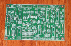
Here's an opportunity to purchase a professionally manufactured PCB for your MPS project.
This dual sided, silk screened PCB is available now at electro-music.com. Just click the electro-music logo to purchase your PCB.
Notice that the CV input is normalled to a switch - the "Noise/Impact" switch. This feature allows the Shell VCO to be modulated from either the impact oscillator or the filtered noise when a plug is not inserted into the CV input. Modulating the shell VCO with noise allows one to set up some nice sizzling cymbal/open high-hat type voices, and selecting the impact oscillator allows variation of the impact timbre by briefly modulating it with the impact oscillator output.
Moving to the right is the Range control, which controls how much, if any, effect the CV, noise or impact oscillator will have on the pitch of the Shell VCO. Note that the Shell VCO has two other inputs routed to it. One is the sweep input, which allows a controllable amount of the Shell envelope generator to bend the pitch up (providing anything from realistic acoustic drum effects to space-age-disco-era electronic drum effects), and there is a pitch control to allow the initial pitch of the shell VCO to be set.
The output of the Shell VCO goes to one input of a balanced modulator, or "ring modulator", which brings us to another feature of the MPS - its ability to clank and clang is derived from ring modulating the Shell VCO with another VCO, which happens to feed the other input of the ring modulator. The ring modulator can be balanced or unbalanced, permitting more or less of each oscillator's tone to "bleed through" the ring modulated tone, allowing even more variation in timbre. This section is absolutely indispensable for creating those solid metallic sounds of the cowbell family in addition to a red shirt getting the old phaser-on-kill effect when the MPS is in locked mode.
Moving to the middle section of the block diagram unearths what really makes the MPS stand out, in my opinion - the Impact Oscillator. The Impact Oscillator is a VCO that provides a pulse wave output. It's designed, when not in lock mode, to provide the very short impact burst that is traditionally derived from the trigger pulse. As mentioned before, rather than filter the trigger pulse, this oscillator actually provides a very short tone burst that can create truly gut-wrenching impact effects. It too has controls that allow its pitch to be swept by the Impact Envelope Generator in addition to a control which allows the initial pitch to be set. The Impact VCO is then fed through a VCA which is also controlled by the Impact Envelope Generator.
At the bottom of the block diagram is the noise section. The noise is fed through a noise filter, which can be selected to have a low pass response or a band pass response. There is a control available to set the resonance of the filter. The filter can also be swept using the Noise Envelope Generator, and the initial cutoff or center frequency can be set with the center control. The filtered noise passes through a VCA which is controlled by the Noise Envelope Generator.
All three sections are then sent to a set of output jacks that allow the signal to be tapped and further externally processed. These jacks are normalled to the mixer input jacks, so that if no plug is inserted in the jacks, the signals will then go to the mixer section.
The mixer input jacks allow a signal to be inserted into the mixer, such as if the noise signal were to be routed out through a phase shifter and then be reinserted into the MPS output, for example. These signals are then mixed to produced the MPS output. The MPS output can be tapped as either a direct output at synth level, or a lower level for direct insertion into an amplifier, for example.
The MPS Trigger and Noise Section - Bang and Sizzle
 |
Here's a description of Sheet 1 in Thomas Henry's own words:
The MPS has been designed to be fired by a trigger, following the usual synthesizer standard of 0 to +5V and 5 milliseconds wide. However, thanks to the "Sensitivity" control it is possible to accommodate a broad range of signals. The trigger is applied to jack J1, where it is differentiated by C3 and R94. IC6a is configured as a comparator and squares up the differentiated signal nicely. With "Mode" switch S1 in the "Triggered" position, R36 sets a threshold for the comparator. You can adjust this to cleanly fire the MPS on weak signals, and yet avoid false triggering on hot ones. The output of IC6a then goes to the three envelope generators in the module.
If S1 is put into the locked position, then the comparator output is latched high. This keeps all of the envelope generators on, forcing the associated VCAs to remain open. You would employ this setting when wanting to use the MPS as a collection of sound generators to be followed by outboard analog synth modules.
The remainder of Sheet 1 consists of the noise generator section; typically this is used to create explosions and snare sounds. The noise generator proper centers around Q1 and Q2. Q1 is configured as a back-biased diode within the amplification loop of Q2. The white noise output is AC coupled via C16. Since the noise characteristics of transistors vary somewhat, you might want to consider using a socket for Q1. This would make it easy to try out a bunch of different units for clarity and volume without all of the usual soldering and desoldering.
The audio output at C16 is fed to a VCF configured around IC1a and IC1b. The signal applied to an OTA should be kept to a maximum of 20mV peak to peak; this is the purpose of attenuator R61/R11. If you find that your noise transistor is too hot or too weak, feel free to adjust R11 up or down accordingly and monitor pin 3 of IC1a for the 20mV value just mentioned. Of course, since this is noise we're talking about, you'll be looking for an average value on your oscilloscope.
There's nothing too clever in the filter. This is simply a state variable unit and comes more or less straight from the LM13700 data sheet. It is moderately elegant in that it uses the internal buffers, thus cutting down on external op-amps. (Of course, this means that the signal must be AC coupled due to the negative offset created by the buffers, but here we don't care since the rest of the circuit is also AC coupled). C1 and C2 are the tuning caps for the filter. The mode can be set to either band pass or low pass by means of switch S2 which simply taps one of the two outputs. And the filter resonance is adjustable via R78. R46 keeps the unit from oscillating at the extreme, but depending on component tolerances you might still be able to make it howl, so watch the volume of your monitor amp until you get used to everything.
The output of the VCF at S2 then is applied to the VCA, passing through C17. The VCA is built around IC2a. R66 and R9 attenuate the signal appropriately for application to the OTA, while the internal buffer manages the final output. This will pass through C18 and go to the mixer yet to be described.
But let's back up to the envelope generator that controls both the VCF and VCA. The trigger signal, mentioned earlier, comes from pin 1 of IC6a and is steered by means of D1 to the envelope generator built around Q3. (All three envelope generators employ steering diodes to keep them from interacting). When the trigger is fired, D1 will dump a charge on timing cap C22, bringing the envelope generator high almost instantaneously. D1 prevents that charge from bleeding off backwards. The only path for the decay, then, is through potentiometer R95 which lets you set the time desired. Q3 buffers the signal and the final envelope is available on its emitter. The full strength signal (developed across potentiometer R37) goes directly to Q9 which is set up as a voltage-to-current converter. This then controls the VCA mentioned earlier. Keep in mind that all of these OTAs are current controlled devices. By the way, the VCA is linearly controlled, but the envelope generator has an exponential output, so things work out nicely sonically.
R37 also lets you tap off a variable amount of the full envelope to modulate the VCF. We need a more precise linear control here, and that is the purpose of putting the voltage-to-current transistor Q8 in the feedback loop of IC6b. R79 lets you set the center of the filter sweep, while R37 dials in the amount of sweep desired. The output current from the collector of Q8 feeds the control current inputs of the two OTAs. Note that these are simply ganged. According to the data sheet for the LM13700 the individual units within the dual device are sufficiently well matched where we can get away with this (especially in a drum circuit). By the way, it is traditional to put in some sort of reverse voltage protection diode in the current source, but since this is a closed system none is required here. Be very careful if you start dinking with the design.
The MPS Impact and Indicator Section: The Essence of *Thwack*!
 |
Moving on to Sheet 2, Thomas writes this:
The CMOS 4046 is employed as a current controlled square wave oscillator here. Just so you know, when using the 4046 as a voltage controlled oscillator (which is the way most people blindly follow the data sheet) the sweep range is extremely limited. But by jettisoning the usual arrangement and going current controlled we obtain several orders of magnitude more range. Here are the particulars. The usual voltage input at pin 9 is locked on +15V and left there. But pin 11 (which would normally be a resistor to set the base frequency) is now used as a current input. C14 between pins 6 and 7 is the timing cap. The square wave output appears at pin 4 of IC4, and is AC coupled before going to the VCA built around IC2b. The VCA is much the same as the one mentioned above.
The trigger signal from Sheet 1 comes here via steering diode D2, and thence to the envelope generator configured around Q4. This is virtually identical to the one in the noise section, but note that the timing cap (C19) is much smaller now; the secret to making a superior impact sound is to sweep the VCO and the VCA rapidly.
The envelope generator voltage is buffered by Q4, and then converted to a current by Q11 which then controls the VCA. Again, the response will be a musically useful exponential one since the envelope generator is exponential and the VCA linear.
A variable amount of the control voltage can be tapped off of R38; this is the "Impact Sweep" control. Potentiometer R80 sets the basic frequency of the sound. These two control voltages are combined by means of a quick-and-dirty mixer and then applied to the inverting buffer Q10. Finally, the voltage is converted to a current which feeds pin 11 of the 4046.
Not wanting to waste anything, notice how the internal XOR gate of the 4046 is pressed into service as an LED driver. The trigger signal from Sheet 1 is steered via D3 to the pulse stretcher made up of C20 and R88; this will guarantee that the LED lights long enough to be seen. By tying pin 14 of IC4 hot, the XOR gate is transformed into an inverter. Finally, when the output at pin 2 drops low, the LED will illuminate. Drawing current, as used here, is far less taxing on CMOS than supplying current.
The MPS Shell Generator: Boom und Klank
 |
For Sheet 3 of the schematic, Thomas describes the operation thusly:
Moving on to Sheet 3, we find the circuitry for the Shell Generator. This is essentially a VCO, control oscillator, ring modulator, envelope generator and VCA, all in one! Let's see how it works.
The control oscillator is formed around OTA IC3a. This is perhaps the simplest VCO circuit you'll ever see; I ran across it in the data sheet for the LM13700. C13 is the integrating timing cap, while D4 and D5 along with R18 and R32 set the trip points for the comparator. The control current input is at pin 1. Because this is such a simple circuit, the triangle output at pin 8 shows some pip distortion. But that is of no consequence here since we will be using this to deliberately create clangorous sounds with the ring modulator. Q12 acts as a voltage-to-current converter, and R81 sets the audio frequency of the thing.
The output of the control oscillator is AC coupled via C25, and can be tamed with R83, the "Ring Mod Depth" control. This then goes to a mixer composed of IC6c and associated components. Also mixed in is a voltage from R82 which is the "Ring Mod Balance" control. This lets you balance or deliberately unbalance the ring modulator for an immense range of weird clangorous sounds. Note too that the mixer biases the combined signals up appropriately by means of R89. We do not want any negative voltages being applied to the ring modulator input of the XR-2206 at pin 1. Again, this is a closed system and perfectly safe. But do not think about injecting external control voltages here without supplying additional reverse voltage protection.
To get maximum range, we ignore the usual arrangement of the XR-2206 (IC5) and instead configure it as a current controlled oscillator. The timing cap is C15, bridging pins 5 and 6. Pin 7 is the control current input. Pin 8, the alternate current input for FSK work, is unused. Only the triangle wave is needed here, so all of the sine wave pins, 13 through 16, are ignored as well. The three resistors and one capacitor connected to pin 3 establish the proper output bias and amplitude of the triangle wave.
The trigger from Sheet 1 makes it to D6 which then fires the envelope generator. This is identical to what we've seen earlier in the noise generator section, so nothing more need be said about it. The "Shell Sweep" potentiometer taps off a variable amount of the envelope generator and this is combined with a voltage from the "Shell Pitch" control. Note too that an external control voltage can be added in via J7. And as if that weren't enough, this is a patchover jack, and so the impact generator and noise source can also modulate the shell generator; more about that in just a moment.
The mixed control signals are then buffered by Q14 and converted to a current by Q7. The collector of the latter feeds pin 7 of the XR-2206. Observe that with the addition of J7 this is no longer a closed system. However, thanks to the way the voltage-to-current converter has been configured it is impossible for reverse currents to occur. Everything is safe, even in the hands of a knucklehead.
As alluded to earlier, the ring modulator comes along for free within the XR-2206. The output eventually winds it way to pin 2, and thence to the VCA built around IC3b and ending up at the mixer.
The MPS Mixer and Power Section: Mix It All Up
 |
In conclusion, here are Thomas' words concerning the contents of Sheet 4 of the schematics:
Sheet 4 brings all three of the audio sources together. They are mixed by op-amp IC6d, but not before passing through a set of break-jacks. These are your typical loop send/receive sort of things that allow you to add in some external processing individually. For example, a very useful application would be to include some equalization, especially for drum work. But do remember that these are synth level signals, so don't blow up your line level equipment! The output of each generator, jacks J2 through J4, is a nominal 10V peak-to-peak maximum.
You might notice that access to the mixer bus is provided in case you wish to gang other sub-mixes here (through their own input resistors, of course). Speaking of which, R90 through R92 tame the three generators just a bit so that we don't pin the output when running all at full strength. The mixed output is available at J5 undiluted (10V peak-to-peak) and at J6 which can be brought down more closely to a level suitable for running to an amplifier, recorder or mixer.
Finally we now we see the "Shell Modulation Type" switch, S3. This neat idea from Scott Stites lets you modulate the shell resonance with either the impact generator or the noise source for even more spectacular percussive effects.
And there you have it, a whirlwind tour of the MPS. This was one of the more exhausting projects I've ever undertaken, if for no other reason than that the breadboarding and testing stage was a royal pain. Scott's aid was tremendous, from beta testing, double checking, constantly measuring things and just in general helping to keep the enthusiasm up. It took something like fourteen 12 hour days of working and reworking things, trying to hold the parts count down but without sacrificing versatility. I'd like to think that a good compromise was struck between complexity and elegance. And lastly, there were a number of unusual techniques employed throughout the MPS that perhaps had never been used together in a DIY music project before. It was a lot of work that I had hoped to make back some of my expense on (both time and money) but in the end, if other users are able to get some good out of it then I'll feel amply rewarded.
The MPS Parts List - Parts is Parts
 |
The MPS doesn't require anything drastically hard to get your mitts on. Perhaps the only mildly difficult item to find would be the XR-2206, and even they turn up with relatively little searching. In fact, all of the ICs can be found at Jameco.

More information on the MPS can be found in the MPS thread at electro-music.com. You can get there by clicking the electro-music logo.
Click the Magic Smoke logo to go to Magic Smoke, home of the "Electronic Drum Cookbook" and other goodies.