The Dim C/TZF Project
Foreword
When I mention that I use the Dim C/TZF a lot, I really do mean it. A friend of mine mentioned that one could run a snow blower through a Dimension C and get something musical on the other end, and I agree with him.
Still, at this writing (late May of 2010) there are some things I would do differently if I were starting the project again. Though the TZF is wonderful function, I rarely use it as implemented on this design. I don't think it would be missed if I hadn't employed it at all. TZF is a function that deserves its own specialized implementation in order to really pull it off. That is a function that I am reserving for my upcoming HEADLine project.
A second point is, I'm pretty well past the point that I care to clone anything. This project is not strictly a clone, but builds upon the original circuitry of the Boss Dimension C. Working with the HEADLine, I now realize that the space provided by racking this design would have allowed a much greater improvement in headroom without deviating from the chipset. The MN3207 can deliver much greater headroom than I'd previously suspcted - investigation of the datasheet and experimentation on the HEADLine design has proven to me that the MN3207 is not nearly the slouch I always suspected it to be when compared to the earlier MN3007 used in the Roland Dimension D.
Still, having said that, I love this unit, and it will forever remain as it is.
An Adaptation of the Boss DC-2 Dimension C
Occasionally, I stumble across something that really rocks my world, and, if I feel that it's something I can build, I tend to drop everything and go for it. I've experienced that with the Buchla 291 Bandpass Filter, the Korg PS Resonator (when I heard Jeff Pontius' use of it with his MAM RS3), and with the Boss Dimension C.
My first exposure to the Dimension C came from the Synth DIY list. The conversation was about the MN3207/MN3102 BBD chipset, and someone queried about what chorus units used those chips. The Dimension C was brought up, and a link to samples at Modezero was posted.
I listened to them and, well, Holy Moly! That was the sound I'd hear in my head when I thought 'Chorus'. This sound was probably planted there from hearing the Dimension C's big brother, the Roland Dimension D, but it was close enough that I knew I had to try it.
Roland Dimension Effects
What are the Dimensions D and C? They're a type of Chorus pioneered by Roland to give a 'motionless' chorus effect. The effect is less intense than, say, an ensemble chorus made up of three delay lines modulated by a pair of triphase LFO's. In fact, the original Dimension devices were, in some modes, more along the lines of a *subliminal* effect than an outright 'in-your-face' type of effect. You could forget you were actually using the device until you bypassed it.
The Dimension effects use two delay lines as opposed to the three delay lines mentioned above in the ensemble chorus. The delay lines are modulated antiphase to each other by an internal LFO to defeat the perceived rhythmical cycle of the LFO that is common with single delay chorus devices. The end result is a feeling of depth with little apparent motion.
The Dimensions C and D had four modes of operation, selectable from four switches. The modes started from barely perceivable effect (mode 1) through a more intense effect (mode 4).
The Roland Dimension D was a rack-mount unit that had balanced and unbalanced stereo inputs and was capable of processing studio level signals. It utilized the MN3007/MN3101 chipset.
The Boss Dimension C DC-2 was a stompbox that had a single mono unbalanced input, and either a mono or stereo output.
Each device utilized a pair of NE570 companders to render an amazingly quiet performance from the two BBD's. Moreover, the devices use a sophisticated method of equalization to arrive at the crystaline sound that they produce.
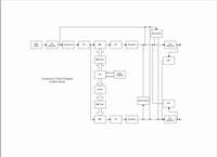
Below is a link to the functional block diagram of the original Boss Dimension C.
From DC-2 Dimension C to Dim C/TZF
This project is by no means done for profit or commercial gain. I would prefer to put the Boss name on the panel of the unit, to give credit to the entity that created the Dimension C, but, at the same time have concern that Boss may not like to have their trademark name on anything they did not build themselves, even if only two of them exist.
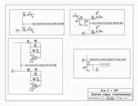
The schematics I have drawn will point, through circled alphabetic indicators, the points in the original schematic that the modifications are applied. I do not feel that I can post the altered version of the original Boss schematic, as it may be copyrighted. The original schematic can be found at the following link:
Dim C/TZF Overview
A number of functions have been added to the original Dimension C design:
Stereo Input
Signal Input Attenuation Potentiometer
Control of LFO Depth and Frequency
Expanded Internal LFO Frequency Range
Manual and Voltage Control of Delay Time
Through Zero Flanging Output
Positive Trigger Bypass
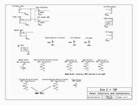
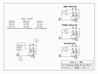
Following is a schematic view of the additional connectors and controls used for the Dim C/TZF
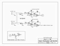
Stereo Input With Signal Buffers and Signal Attenuation
Jeff Pontius, who designed the panel pictured above, and I decided early on to build a rack mount version of the Dimension C. Having the space of a rack mount panel, thoughts began turning to "what else can this thing do?". The original Dimensions had little more than a bypass switch and the four mode switches.
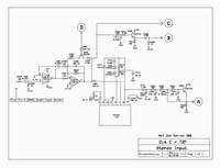
First off, I began exploring the differences between the Dimension C and Dimension D. One obvious difference is that the Dimension D can process stereo input signals. Soon, it became obvious that all the points were present in the Dimension C to allow the same functionality. The Dimension C even had an unused half of an NE570 that could be used as the compressor for the added channel! So, that's exactly what I did.
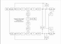
Below is a link to the block diagram of the Dimension C with stereo input.
A fantastic function shared between the two Dimension devices is the ability to accept a mono signal and render it wonderfully in stereo. I retained this function with the Dim C/TZF by using a switching jack for the 'Right' input. With no plug inserted into this jack, it routes the mono input down the 'stereo' path for mono to stereo conversion. This also preserves the mono output function of the original Dimension C (I do not believe the Dimension D had this function, BTW).
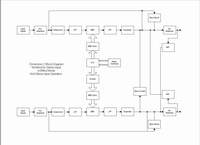
Below is a link to the block diagram of the Dim C in mono operation, with the added stereo input circuitry in place.
In order to better handle the output impedance and levels of the synth, I added input buffers consisting of NE5532's. I also have added an input attenuator consisting of a dual ganged 100K linear pot. Below are links to the schematics for both the input buffer and stereo input.
Mode and Internal LFO Control
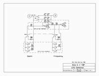
Next up were the operating modes themselves. The Dimension C Mode switches are DPDT. One pole places a resistance in parallel with the timing resistor of the LFO to alter the frequency of the LFO, and the other pole places a resistance in parallel with the output resistor of the LFO in order to affect the depth of modulation. My hat is off to the Roland/Boss engineers - they certainly found the prime sweet spots of the devices.
But, still, there does exist a spectrum of effect between these modes. This was easily provided for by putting in pots in parallel with the above mentioned resistors. But - a few of the modes actually *open* the parallel resistances, and a pot will not quite get there, so the solution to this was to have three of the original mode switches (more on that in a bit), plus an additional switch that selected the mode switches or the pots for control of LFO frequency and depth.
What is it with only three mode switches when the original Dimension C had four modes of operation? Quite simply it's this: the original Mode 1 switch switched *nothing* - it was there so that both the frequency and depth resistors could have infinite resistance placed in parallel with them with the switch assembly used by Boss. Because I am not constricted to a single switch assembly (we're going to use toggle switches), putting in a switch to switch nothing obviously would have been useless. So, the way it works is that with all three of the mode switches in the 'off' position, *that* is Mode 1. With mode switch one only in the on position, that is Mode 2. With mode switch two only in the on position, that is Mode 3, and with mode switch three only in the on position, that is Mode 4. Note that, unlike the original Dimension C, different mode switches can be on at the same time, giving a bit more variation with mode switch operation.
The fourth switch is a switch that disconnects the effect of the three mode switches and applies the settings of the frequency and depth pots. When this switch is applied, only the frequency and depth pots will affect the Dim C/TZF operation. One use for this could be the setting of a 'custom' mode that could be accessed with the flick of a switch. This configuration not only preserves the original functionality of the Dimension C mode selection, but expands upon it.
Another switch was added to provide more range to the LFO settings. Increasing the LFO rate beyond the original function provided very, well, strange effects. Lowering the frequency, however, brought a whole new dimension to the sound - a very nice, smooth effect indeed. It's still possible, with this implementation of the Dimension C to get those bizarre effects, but that is mentioned later. Right now, the switch being discussed provides two additional ranges of frequency below the original LFO range.
Below is the link to the schematic on how the mode selection, pot control of depth and frequency, and LFO frequency range functions were implemented.
The switch used to select between the mode switch and pot operation is a standard two position DPDT switch. The switch used for selection of the LFO frequency range is actually a three position C&K 7211 DPDT switch. A detail of how it works is shown at the following link.
Manual and External Voltage Control of Delay Time
The next step was to add some 'modular' power to the Dim C/TZF - voltage control of the delay time itself. This provides a means of overcoming any limitation of LFO frequency or LFO waveform, so, for one thing, those 'crazy' sounds mentioned before are certainly accessible. But, aside from weird sounds, I've found that voltage control of the delay times also adds a whole spectrum of effect - especially when one considers synchronization with other functions, or applying voltage control other than an LFO to the device. Envelope generators, for example, reveal a whole new side when controlling the delay time. VCO's provide audio rate modulation of the delay, which is a much more 'in your face' effect than the Dimension C was ever envisioned to be. Even when using an LFO, you have a choice of the waveform that is used to modulate the delay time of the Dim C/TZF.
To be useful, implementing CV obviously required an input attenuator for the voltage input, and I was struck with the idea of providing a dual use for that pot - with no CV applied to the Dim C, this pot could be used as a manual control to set the delay times to a static setting.
What use would this provide? During my earlier experiments with BBD based comb filters, I found that a static setting of the delay time could render different tonalities, or 'resonances' to a signal - rather like an unusual filter bank or like setting a static phase using a phase shifter.
Another thing that spurred this thought was the TZF output, and a conversation of symmetrical versus asymmetrical modulation of the flange effect that occured on the DIY stompbox list. The thought was that if one only modulated one of the delay lines, then the perceived through-zero effect could be set to occur at any point of the sweep of the moving delay. Actually, I had a basic misunderstanding about how this would work, or what Mark Hammer and Mike Irwin were getting at. The through-zero point could still be adjusted to occur at the 'end' of the sweep or closer to the middle still with both delays being modulated, but Mark's point was that coming up with an LFO wave with the proper hypertriangular shape would present some challenges to the concept. In any event, my experimentation did result in getting quite a variety of different sweep effects by sweeping only one of the delays. That, and the perceived sweep of the delay was longer because only one of the delays was moving.
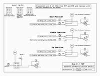
From this line of thought, an additional control was added - a switch that performs three functions. In position 1, the switch allows control of both delay lines by the internal LFO. In position 2, the switch allows control of one of the delay lines by either the applied control voltage or to be set at a fixed delay if no control voltage is applied. The other delay is still swept by the internal LFO in this position. In position 3, both of the delay lines are controlled antiphase to each other by either the applied CV, or if no CV is applied, their delay time is set by the CV attenuator/manual control. Being that the control acts on the delays in antiphase, moving this control has the effect of spreading the delay times in relation to each other.
If I would have had + and - voltage supplies available to me, it would have been very easy and quick to accomplish this, but because the Dim C internally runs off of +9V and ground, this presented a learning curve to me - I'd never really dealt with unipolar synth circuits before! Eventually I came across a design that works quite satifactorily for the application, though it may seem a bit odd to the more experienced.
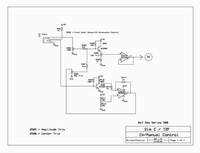
For the manual control, I connect 9V to the normal input of the CV input jack through a 1K protection resistor. This is applied through the External CV/Manual Control pot to the base of Q501. The CV input jack is a stereo jack, so when a plug is inserted into it, two things happen: the signal on the plug is applied to the base of Q501 and the base of Q502 is grounded, causing comparator U501A to rail positive, which applies an offset to the base of Q501, allowing bipolar CV's to control the frequency of the BBD clocks.
Following is the schematic for the CV/Manual switch and the interconnect into the main Dimension C circuit.
TZF: Through-Zero Flanging
To begin with, a quick note on what Through Zero Flanging (TZF) is. Flanging was born as a studio trick and can be heard on any number of popular songs - The Doobie Brothers' "Listen to the Music" or the Eagles "Life in the Fast Lane" are a couple that come to mind, along with the Small Faces classic "Itchy Koo Park". The technique involves putting two copies of the same track on two different tape machines, and mixing them together onto a third tape machine. Varying the play speed of one or both of the tape machines resulted in the swooshing sound that is flanging. The word flanging itself refers to the practice of slowing one of the reels down by placing a thumb against the flange of the reel.
TZF refers to the technique of one of the reels going faster or slower than the other reel, so that the material on that tape occurs slightly before and after the material on the other tape. When the two tapes are exactly in sync, no effect is heard, but as material on one tape approaches then passes the other tape in time, the intense jet plane swoosh can be heard swooshing 'in' then swooshing 'out', with the zero point unaffected, and appearing more or less 'in the middle' of the effect.
Using BBD's for TZF has always been a bit problematic. To achieve TZF, one BBD has to delay the original signal so that the other BBD can move 'before' and 'after' the delayed signal in time. This implies that the clocks of the BBD's must 'cross' each other. This normally results in annoying heterodyning between the clocks.
Having said, that multi-BBD chorus effects all have TZF built into them - the BBD's are constantly crossing themselves in time. When I first looked at the Dimension C schematic, I realized that somewhere in there, TZF was occuring, and had all of these complicated ideas about how to extract it. It was Mike Irwin who found a simple, yet effective method of getting a TZF response out of it. He found that passively mixing the outputs of the expander together resulted in a satisfying TZF effect. So that's what I did, and it works wonderfully as an 'extra' output to the Dim C/TZF.
Mike's original idea was to have a trimmer in the passive mixer to maximize the notch, but I was never able to make it sound any deeper (to my ears) than two equal value resistors, so I just stuck with that. Another thing about the TZF output - the two signals have gone through pre-emphasis tilting them to the treble side of the audio spectrum, and I originally was going to run the signal through de-emphasis, but I found the flanging to be more prominent without de-empahasis, so I left the de-emphasis out. Hence, the TZF output is a 'brighter' output than the chorus outputs.
All kinds of enhancements sprang to mind, such as positive and negative regeneration, more control of the individual delay lines, etc, but figured out pretty quickly this extra control fast outgrew the front panel, so a dedicated TZF module is in my future. I settled on the one unique 'TZF' output and am quite happy with it.
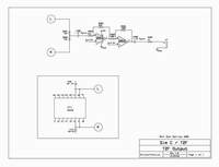
Below is the schematic to how the TZF output was implemented.
Effect Bypass Circuit
When I decided to build the Dimension C, I chose to see if I could find as many of the original parts as possible. This really isn't necessary, as Mike Irwin has proven that effective substitute parts will work nicely, but, at the same time, I figured I'd be lucky enough to get the thing working with the original parts.
So, the core of the Dimension C has as many of the original parts that I could find. The exceptions are as follows:
For 3V zeners, I used 1N5225's, for 5.1V zeners, I used 1N5231B's, for the power protect diode, I plan to use a 1N4002, and for the bypass flipflop, I am using a CD4013 - I could not find a BA634 to save my life.
Debouncing the 4013 proved to be quite a challenge for me. My test of the switch is actually a foot operated normally open momentary switch, and a very noisy beast at that for the 'trial by fire'. After a lot of experimentation, I finally wound up with very effective de-bouncing.
Jeff and I decided to add a bypass input that would toggle the bypass with a positive trigger pulse rather than a foot operated switch, making it controllable with modules from our synthesizers. I added the circuitry to do that, and found that not only triggers would activate the bypass, but also LFO's and VCO's. This actually provides an additional means of modulation - modulating the bypass at audio rate frequencies introduces a sort of AM effect.
One additional comment - I have no idea what color the original 'Check' LED (LN-28RP) was, but Jeff and I decided to use red as the power LED and green as the 'active effect' LED, so the original LED has been replaced with a green LED.
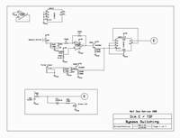
Below is the schematic for the Dim C/TZF bypass circuit.
Power Entry and Regulation
The plan is to power the Dim C/TZF with a wall wart supply, most likely a 12V supply. The power entry jack to be used will be a commonly available 3.5mm connector, and will mount on the outside of the PCB enclosure.
There will be an on-board 9V regulator and filtering caps to ensure hum-free operation. Until I have had a chance to try the target wall wart device, I will not have a complete schematic for that section.
Sound Samples
Here's a multi-tracked sample of processing the modular synth through the Dim C/TZF using external triangle LFO modulation. At the beginning of the sample, low frequency noise is processed through the TZF output with an extremely low modulation. After that, a bit of higher freq noise is sent along the same path with the Dim C being modulated at a faster rate. During and after that, mixed in is some ring modulation and frequency modulation of the VCO's through the filter, through the normal Dimension C output. All tracks are run through the Dim C, in Mono In/Mono Out mode.
The PT2399 and tank reverb of the Fender Sidekick were used to give some ambience to some of the tracks as well.
Here's a sample of the Dim C modifying the timbre of a modular patch.
The patch consists of the Buchla 291+ filter processing a mix of two sawtooth VCO's. The VCO's and the filter are being controlled by the sample and hold circuit from the Buchla 266 Source of Uncertainty module. The sample and hold is sampling a triangle LFO and is being clocked by a second pulse wave LFO. The 'normal' sample and hold output is modulating the bandwidth input of the 291 filter. The two alternating outputs of the sample and hold are connected to the expo CV input of each VCO. One of the alternating triggers from the sample and hold is triggering an AR envelope generator, which is modulating the frequency input of the 291 filter. The low pass output of the filter is fed through a VCA, which is also controlled by the envelope generator, into the Dim C. The Dim C is being modulated by a third triangle LFO. The pulse wave output of this same LFO is being sent to the FM input of the filter. The output of the Dim C is going to the recorder.
The sample starts out with the Dim C bypassed. At 00:30, the Dim C is unbypassed and remains on until 1:19.
Here is a multi-track composition using variations of the above patch. The 266 S&H circuit is the only controller used throughout the patch. It appears the Dim C can really enhance the modular!
The next sample is of the Dim C processing my Korg DW6000. The Dim C is in mono to stereo mode and is being modulated by an external triangle LFO. The LFO is quite slow and is modulating the Dim C throughout the full CV range, so this really would be analagous to Mode 2. This is an example of the Dim C in its more subtle mode, adding a nice coloration to the sound.
It's just the DW6000 through the Dim C into the recorder, no other effects used.
00:00 Starts out in bypassed mode.
00:38 Effect is switched on.
1:27 the effect is bypassed.
1:40 In effect mode again for the short blip at the end.
This sample is just some noodling with various patches of the DW6000, using the same patch/settings as above.
Here's a sample of the Dim C doing two things the original Dimension C did not do: Processing a stereo input and modulating the delay lines with a fast pulse.
Both left and right outputs of my Korg DW6000 are patched to the Dim C stereo inputs, and the left and right outputs are going straight to the recorder (no other effects are used in the chain). A pulse LFO is patched into the CV input of the Dim C.
00:00 The sample starts out with the chorus of the DW6000 off, which is a mono signal, so the beginning is in mono. At the beginning the Dim C is also bypassed.
00:21 I switch the chorus of the DW6000 on, converting it to a stereo signal.
00:38 I un-bypass the Dim C. After that, as the sample progresses, I use the Dim C's CV Level pot to increase the level of CV for a while, then towards the end I back it off, lowering the level of CV. The end result is a stereo signal being sharply modulated in stereo.
Test Sample - Dim C 002. DW6000 through Dim C to Recorder (no other effects). Mono input, stereo output.
00:00 Uneffected DW6000 (bypass mode)
00:32 Mode 1
01:09 Mode 2
01:56 Mode 3
03.01 Mode 4
Here's a sample of the Korg DW6000 being processed by the Dim C TZF function. There are six tracks of voices being modulated by various rates and depths of flanging.
Here's an interesting sample that more-or-less exposes the effect of the DC-2 chorus. The sample is divided into three parts:
The first part is the DW6000 dry.
The second part is the same DW6000 voice, but modulated by the Dim C in Mode 4.
The third part is still the same DW6000 voice, but now only the right channel, wet, can be heard.
Notice the modulation is actually *not* a smooth sinusoidal shift up and down, but appears rather more trapezoidal in nature. It's truly amazing to listen to 'one side' of the chorus, then kick in the other side - the transformation is nothing short of magical, IMO.

